Preparation, Control panel – Sealey SCI6S User Manual
Page 3
4. PREPARATION
WARNING!
RISK OF CONTACT WITH BATTERY ACID. BATTERY ACID IS A HIGHLY CORROSIVE SULPHURIC ACID.
4.1.
Remove all cord wraps and uncoil the cables prior to using the battery charger.
4.2.
If it is necessary to remove the battery from the vehicle to charge it, always remove the grounded terminal first. Make sure all of the
accessories in the vehicle are off to prevent arcing.
4.3.
Clean the battery terminals before charging the battery. During cleaning, keep airborne corrosion from coming into contact with your
eyes, nose and mouth. Use baking soda and water to neutralise the battery acid and help eliminate airborne corrosion.
DO NOT touch
your eyes, nose or mouth.
4.4.
Add distilled water to each cell until the battery acid reaches the level specified by the battery manufacturer.
DO NOT overfill. For a
battery without removable cell caps, such as valve regulated lead-acid batteries (VRLA), carefully follow the manufacturer’s recharging
instructions.
4.5.
Read, understand and follow all instructions for the charger, battery, vehicle and any equipment used near the battery and charger.
Study all of the battery manufacturer’s specific precautions whilst charging and their recommended rates of charge.
4.6.
Determine the voltage of the battery by referring to the vehicle’s manual. This charger is equipped with Auto Voltage Detection of
6 or 12 volts.
4.7.
Make sure that the charger cable clips make tight connections.
4.8.
Charger Location.
WARNING!
RISK OF EXPLOSION AND CONTACT WITH BATTERY ACID.
4.8.1. Locate the charger as far away from the battery as the DC cables permit.
4.8.2. Never place the charger directly above the battery being charged; gases from the battery will corrode and damage the charger.
4.8.3.
DO NOT set the battery on top of the charger.
4.8.4. Never allow battery acid to drip onto the charger when reading the electrolyte specific gravity or filling the battery.
4.9.
Follow these steps when the battery is installed in a vehicle.
WARNING! A SPARK NEAR THE BATTERY MAY CAUSE A BATTERY EXPLOSION. REDUCE THE RISK OF A SPARK NEAR
THE BATTERY.
4.9.1. Position the mains and DC cables to reduce the risk of damage by the bonnet, door and moving or hot engine parts.
NOTE: If it is
necessary to close the bonnet during the charging process, ensure that the bonnet does not touch the metal part of the battery clips or
cut the insulation of the cables.
4.9.2. Stay clear of fan blades, belts, pulleys and other parts of the engine that can cause injury.
4.9.3. Check the polarity of the battery posts. The POSITIVE (POS, P, +) battery post usually has a larger diameter than the NEGATIVE (NEG,
N, -) post.
4.9.4. Determine which post of the battery is earthed (connected) to the chassis.
4.9.5. For a negative-earthed vehicle, connect the POSITIVE (RED) clip from the battery charger to the POSITIVE (POS, P, +) non-earthed
post of the battery. Connect the NEGATIVE (BLACK) clip to the vehicle chassis or engine block away from the battery.
DO NOT connect
the clip to the carburetor, fuel lines or sheet-metal body parts. Connect to a heavy gauge metal part of the frame or engine block.
4.9.6. For a positive-earthed vehicle, connect the NEGATIVE (BLACK) clip from the battery charger to the NEGATIVE (NEG, N, -)
non-earthed post of the battery. Connect the POSITIVE (RED) clip to the vehicle chassis or engine block away from the battery.
DO
NOT connect the clip to the carburetor, fuel lines or sheet-metal body parts. Connect to a heavy gauge metal part of the frame or engine
block.
4.9.7.
Connect charger mains cable to mains supply.
4.9.8. When disconnecting the charger, disconnect from the mains supply, remove the clip from the vehicle chassis and then remove the clip
from the battery terminal.
4.10. Follow these steps when the battery is removed from the vehicle.
WARNING! A SPARK NEAR THE BATTERY MAY CAUSE A BATTERY EXPLOSION. REDUCE THE RISK OF A SPARK NEAR
THE BATTERY.
4.10.1. Check the polarity of the battery posts. The POSITIVE (POS, P, +) battery post usually has a larger diameter than the NEGATIVE
(NEG, N, -) post.
4.10.2.
Attach at least a 24-inch (61 cm) long 6-gauge (AWG) insulated battery cable to the NEGATIVE (NEG, N, -) battery post.
4.10.3.
Connect the POSITIVE (RED) charger clip to the POSITIVE (POS, P, +) post of the battery.
4.10.4.
Position yourself and the free end of the cable previously attached to the NEGATIVE (NEG, N, -) battery post as far away from the
battery as possible, then connect the NEGATIVE (BLACK) charger clip to the free end of the cable.
4.10.5.
DO NOT face the battery when making the final connection.
4.10.6.
Connect charger mains cable to a mains supply outlet.
4.10.7.
When disconnecting the charger, always do so in the reverse order of the connecting procedure and break the first connection while as
far away from the battery as practical.
4.10.8.
A marine (boat) battery must be removed and charged on shore. To charge it onboard requires equipment specially designed for marine
use.
NOTE: See the Operation section for a complete description of the charger modes.
5.1.
Charge Rate Button.
5.1.1.
Use this button to set the maximum charge rate. Press the button until the desired
charge rate is selected.
– Charges and maintains small batteries. Maintains large batteries.
– Charges small batteries, such as those commonly used in garden
tractors, snowmobiles and motorcycles.
NOT for charging large batteries.
– Charges automotive, marine and light truck batteries.
NOTE: Once the charger has started charging the battery; if the Charge Rate button is pressed
once, the output current is shut off. If the Charge Rate button is pressed again,
the current will go back on at the same setting it was when it was turned off.
For example: The charger is charging a battery at the fast charge rate setting.
If the Charge Rate button is pressed, the output is turned off. If the Charge Rate button
is pressed again, the output will turn back on at the fast charge rate setting.
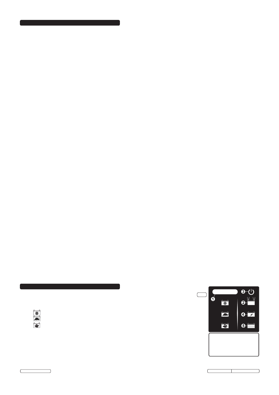
5. CONTROL PANEL
Fig.2
1.Charge rate button
2.Connected LED Symbol
3.Power symbol
4.Charging LED symbol
5.Battery full LED symbol
Original Language Version
SCI6S Issue: 1 - 21/05/14
© Jack Sealey Ltd