Fig.5, Fig.6 fig.7 fig.8, Maintenance (pump) – Sealey EWP050 User Manual
Page 3: Maintenance (engine)
5.1.5 Rotate the engine switch clockwise to the ON position. See fig.5.
5.1.6 Fig.4 shows the fuel tap in the OFF position. Push the fuel tap
over to the right to the open position.
5.1.7 If the engine is cold move the choke lever to the left to close
the choke.
5.1.8 Move the throttle lever left to the fully open position then
ease it back slightly, fig.4 shows the throttle in the fully
closed position.
5.1.9 Take hold of the recoil starter handle (see fig.5) and pull it
slowly until you feel resistance, then let it return slowly.
5.1.10 Now pull the starting handle hard and fast all the way out. Use
two hands if necessary.
5.1.11 If the engine doesn’t start repeat the process from 5.1.8.
5.1.12 Once started adjust throttle lever to the required setting and
return the choke to the open position when the engine is
warm.
5.2. SHUT DOWN PROCEDURE.
5.2.1 When pumping has finished stop the engine by pushing the
throttle lever fully to the right. (See fig.4) and turn the engine
switch to the OFF position.
5.2.2 Turn off the fuel tap. (See fig.4)
5.2.3 In an emergency turn the engine switch to the OFF position.
fig.5
6. MAINTENANCE (PUMP)
Maintenance should only be performed with the engine turned
off and the unit disconnected from the inlet and outlet pipes.
6.1 WINTER STORAGE: To prevent ice damage to the pump
during winter storage drain water out of the pump by removing
the stopper from the drain port seen in fig.2. Replace the
stopper when all water has drained out.
6.2 PUMP SEALS: During the course of the working life of the
pump it may be necessary to replace the pump seals. If this
service is required the unit should be returned to your local
Sealey dealer for maintenance by qualified engineers.
7. MAINTENANCE (ENGINE)
7.1 Change engine oil after the first 20 hours of operation.
Thereafter, change oil every six months or every 100 hours of
operation. Change oil more often if engine is operated under
heavy load, or in high ambient air temperatures. Top-up with
an SAE10W30 oil. Failure to change the the oil according to
the conditions defined above will invalidate your warranty.
7.3
CHANGING THE OIL.
7.3.1 Operate the engine for 3 minutes to warm the oil and then
stop the engine using the shut down procedure described in
section 5.2. Place a suitable container below the frame,
remove the plug and allow the oil to drain. Replace the drain
plug and refill with fresh oil. Check the oil level using the
dipstick. Dispose of the old oil according to local authority
guidelines.
7.4
FUEL FILTER: The fuel filter is in the neck of the fuel tank.
Clean it every 300 hours.
7.5
AIR FILTER. To access the air filter element unscrew and
remove the wing nut on the top of the cover. Lift the air filter
cover (1) off its threaded mounting rod
7.5.1 Remove the foam filter (2) from the air intake base moulding.
7.5.2 Wash the foam element with a household detergent or a high
flash-point solvent and squeeze dry. When the element is
thoroughly dry soak it in clean engine oil. Squeeze out any
excess oil, fit back over the air intake base moulding.
7.5.3 Place the air filter cover onto the threaded rod and secure with
the wing nut.
7.5.4 The foam element should be replaced after every 300 hours of
service.
at the lowest level or below, top-up immediately with an
SAE10W30 oil.
7.2.3 Screw dipstick fully home to seal oil fill hole.
7.2
CHECKING THE OIL LEVEL. Ensure the unit is on a level
surface.
7.2.1 Unscrew the dipstick/oil filler cap (see fig.5) and wipe it
clean of oil. Note that the maximum oil level should be just
below the opening of the filler neck.
7.2.2 Check the oil level by seating the dipstick into the hole
without screwing it in. See fig.6. On removal the oil level
should be between the two marks on the dipstick. If it is
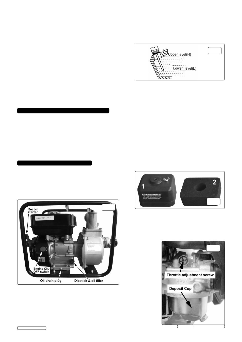
7.6 CARbURETTOR. To adjust the idling speed, turn the throttle
adjusting screw (fig.8) clockwise to increase and anti-clockwise
to decrease engine speed. Standard idling speed:
1700 +/- 15rpm
7.6.1 To clean the deposit cup (fig.8), set the fuel tap to OFF,
undo the central
bolt and lower
the deposit cup,
take care not to
spill any fuel,
dispose of old
fuel in
accordance with
local authority
guidelines. Wash
components in
non-flammable
or high flash point
cleaning solvents,
dry components
and refit
components
in reverse order.
Turn fuel tap back
ON and check for
leaks.
fig.6
fig.7
fig.8
© Jack Sealey Limited
Original Language Version
EWP050 Issue No.3(I) -14/08/13