Installation – MCZ Ego 2.0 AIR User Manual
Page 16
A
B
B
A
C
MIN.1,5 m
MIN.1,5 m
MIN.1,5 m
MIN.0,3 m
14
2-INSTALLATION
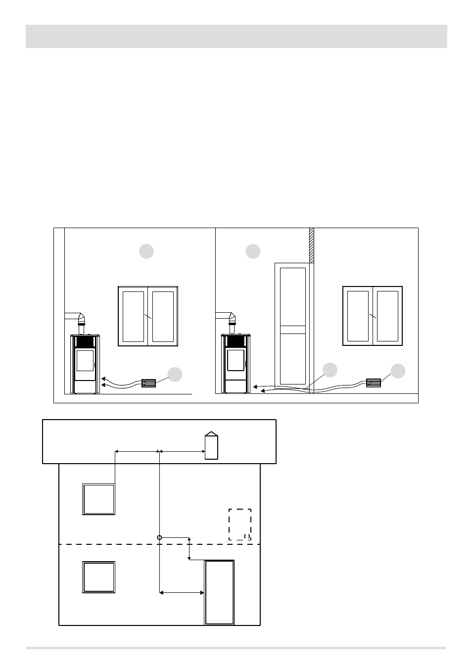
EXTERNAL AIR INLET
It is mandatory to provide an adequate external air intake that supplies the combustion air required for the product to work properly. The
flow of air between the outside and the installation room may be direct, through an inlet in an external wall of the room; or indirect, via
air intake from adjoining rooms and connecting permanently with the installation room (see Figure 9 b). Adjoining areas may not include
sleeping areas, garages or general areas with a fire hazard. During installation one must check the minimum clearances required for air
intake from outside. Take into account the presence of doors and windows that could interfere with the proper flow of air to the stove (see
diagram below).
The air intake must have a minimum total net area of 80 cm2: the surface must be increased accordingly if within the room there are other
active generators (for example: electric fan for stale air extraction, kitchen hood, other stoves, etc...), which could cause cause depression
in the room. One must verify that, with all the equipment on, the pressure drop between the room and the outside does not exceed a value
of 4 Pa. If necessary increase the intake section of the air inlet, which must be made at floor level and always protected with a bird-proof
outer protection grid and in such a way that it cannot be obstructed by any object.
It is possible to connect the air required for
combustion directly to the outside air inlet,
with a pipe of at least Ø50mm, with maximum
length of 3linear metres; each pipe bend shall be
considered equivalent to a linear metre. To attach
the pipe see the back of the stove.
For stoves installed in studio flats, bedrooms and
bathrooms (where allowed), it is mandatory to
connect the combustion air outside. In particular
for sealed stoves the connection must be sealed
in order not to compromise the overall sealed
characteristic of the system.
FIGURE 9 A - DIRECTLY FROM OUTSIDE
FIGURE 10
FIGURE 9 B - INDIRECTLY FROM THE ADJACENT ROOM
A=AIR INLET
B=ROOM TO BE VENTILATED
C=INCREASE OF THE GAP UNDER THE DOOR