Marwin Valve KC Series Trunnion Valves User Manual
General information, Installation, Kc trunnion series
3170 Wasson Road • Cincinnati, OH 45209 USA
Phone 513-533-5600 • Fax 513-871-0105
[email protected] • www.marwinvalve.com
KC Trunnion Series
Installation & Maintenance Instructions for
Marwin KC Trunnion Series
Warning: Marwin Valve ball valves must only be used, installed and repaired in accordance with these Installation & Maintenance Instructions.
Observe all applicable public and company codes and regulations. In the event of leakage or other malfunction, call a qualified service person;
continued operation may cause system failure or a general hazard.
Please read these instructions carefully!
Your Marwin Valve product will provide you with long,
trouble-free service if it is correctly installed and main-
tained. Spending a few minutes now reading these
instructions can save hours of trouble and downtime
later. When making repairs, use only genuine Marwin
Valve parts, available for immediate shipment from the
factory.
General Information
This article describes the procedure of Site Installa-
tion, Operation and Maintenance for the KC Trunnion
valves. The valves are designed, manufactured and
tested in accordance with API 6D unless otherwise
specified. Flanged ends are in accordance with ASME
B16.5 (for valve nominal size 24" and smaller) and
ASME B16.47a/b (for valve nominal larger than 24").
Note: Both 16.47a and 16.47b are available. Please
make clear when ordering.
The KC Trunnion valves are bi-directional as standard
design which allows for the valves to be installed for
flow in either direction.
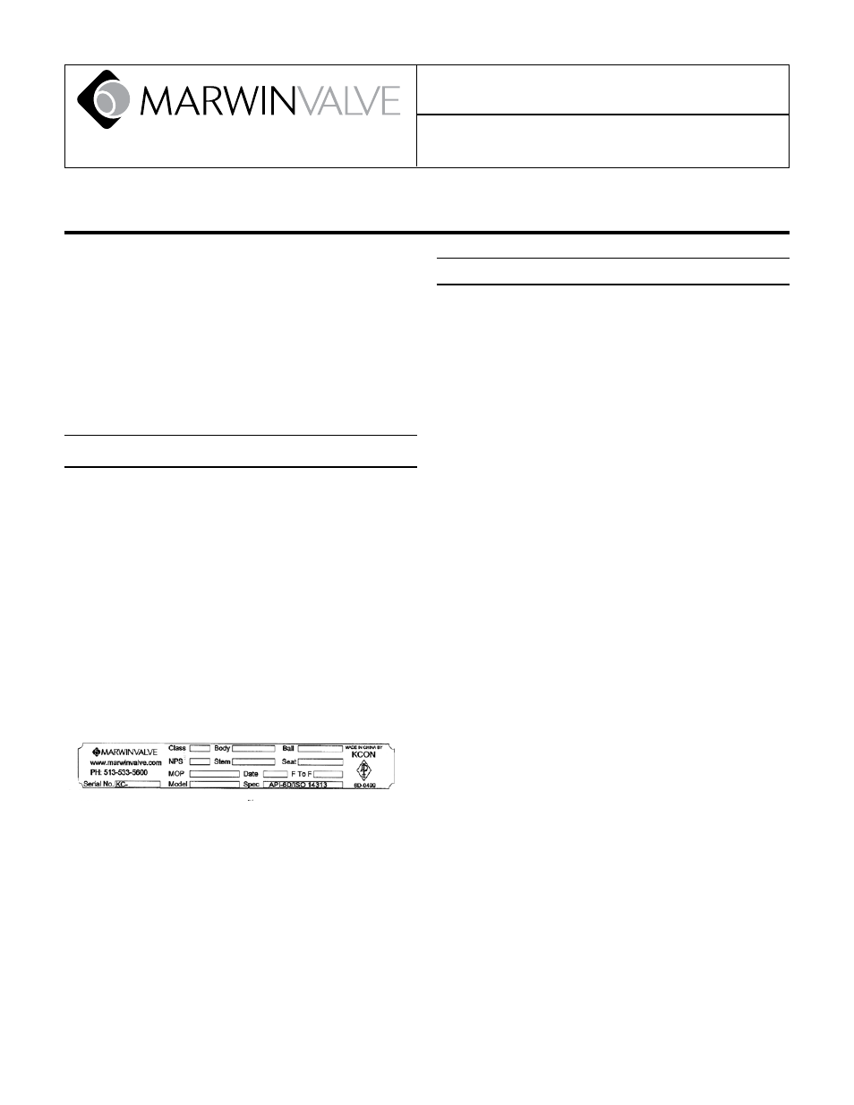
Identification:
All Marwin valves are identified by the Name plate
which includes the following information:
1. Type (This stands for the type of the valve which
can be described in BV for ball valve).
2. NPS/Class (This stands for the nominal size of the
valve unit in inches and the pressure rating of the
valve in API 6D Class)
3. Body/Trim/Seat (This stands for the material which
is used by Body/Trim/Seat)
4. Date (The date of manufacture of the valve in Year
and Month)
5. Spec. (This stands for the design standard which
the valve meets and the Serial no. of each valve)
Installation
Unpacking:
1. All Valves should be inspected on receipt for lost com-
ponents or damage.
2. Remove end connection protectors and check the in-
terior of the valve and the end connections for damage
or if any unexpected material gets inside the valve.
3. All valves are shipped in the open position to protect
the sealing face.
Handling:
1. Appropriate handling equipment is necessary for valve
weights over 100 kgs.
2. The valve can be lifted by slings, end flange, or the
lift lugs equipped with the valve. Caution: Two lift
lugs are provided, to balance the valve, never use
only one when lifting the valve as this may cause
personnel or equipment injury/damages
).
Installation:
1. Orient valve in piping to allow clearance and allow ac-
cess to the valve Actuator/Operator.
2. Flanged valves should be installed using the appropri-
ate gasket (not included with the valve).
3. Welded valves should be installed using qualified
welders and the weld procedures appropriate for the
valve materials. (Ball valve should be welded in the
open position). Caution: When welding/Preheating/
Stress relieving the body temperature should not
exceed 200°C at any point beyond the welded end
.
4. Before operating the valve from the open position, the
pipe should be thoroughly flushed to prevent any mat-
ter from damaging the sealing surface.
5. After installation and system testing, the valve should
be drained to remove the test fluid.
-1-