Fig. 3, Fig.3, Electronic connections diagram – Medal Sports FH17201 User Manual
Page 7: Fig. 3a fig. 3b
Advertising
6
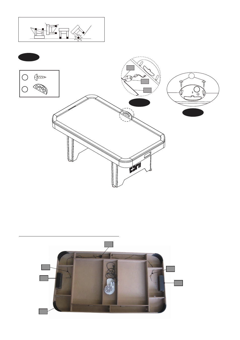
FIG. 3
FIG. 3A
FIG. 3B
DO NOT LEAN THE
TABLE ON ITS LEGS
HOLD TABLE
CABINET
DO NOT HOLD THE LEGS
CAUTION: Two strong adults are recommended to turn the table
over as shown.
1. Lift the table off the ground.
2. Turn the table over.
3. Place it on all four feet at the same time on the ground.
FIG.3
7. Attach the Scorer (#12) to the top rail of the Main Cabinet (#1) using two Screws (#9).
See FIG. 3 & 3B.
8. Thread the Scorer Wire through the hole of the side apron to Insert the Scorer Wire into the Connect
Box (#A3).
See FIG.3A.
X 1
X 2
9
12
12
Electronic Connections Diagram
9
A5
A5
A3
A7
A9
A5
A5
A7
A3
Advertising