Fig.2 – Medal Sports FH1415402 User Manual
Page 8
www.themdsports.com
1415402
7
(Continued on the next page.)
5
6
7
9
10
11
13
14
A4
A5
A7
A8
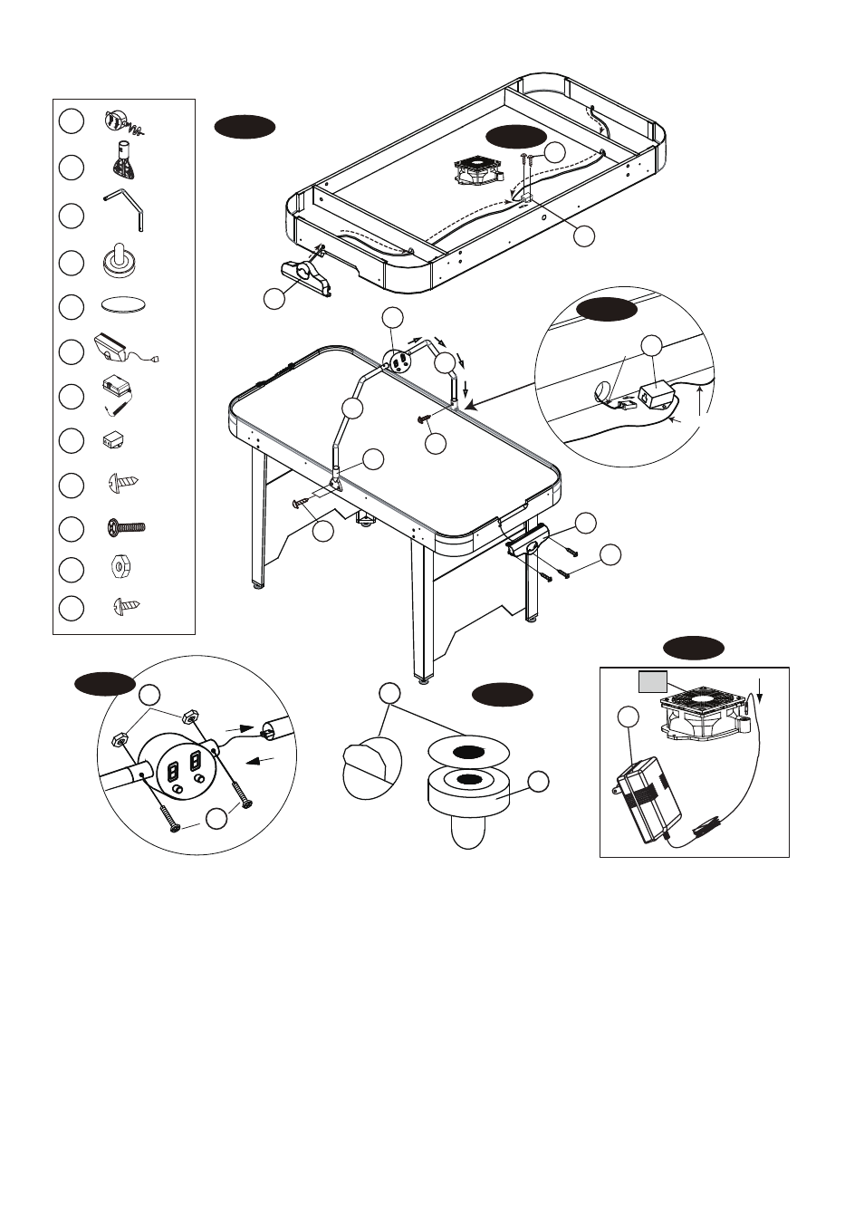
FIG. 3
FIG.2
7. Attach the Connect Box(#14) near the side apron using two Screw(#A8).Thread the wire from Goal Box (#11)
through the openings of the end aprons and support of the playfield to insert the Wire into the Connect Box (#14).
See FIG. 3A & 3C.
8. Attach the Goals (#11) to each End Apron using three Screws (#A4).
See FIG. 3.
9. Attach the Electronic Scorer (#5) to the Scorer Pole (#7) using two Bolts (#A5) and two Nuts (#A7).
Thread the Scorer Wire through the Scorer Pole (#7) and the opening of the side apron to Insert the Scorer Wire into
the Connect Box (#14).
See FIG. 3 & 3B and 3C.
10. Attach the Pole Bracket (#6) to the side apron in the pre-drilled holes using two Screws (#A4) and Insert the Scorer
Pole (#7) into Pole Bracket (#6) using one Screw (#A4).
See FIG. 3.
11. Tear off the backside paper of the Felt Pad (#10) and stick them at the bottom of the Pushers (#9).
See FIG. 3D.
12. Insert the Adaptor (#13) into the DC Motor (#P1).
See FIG. 3E.
X 2
X 2
X 2
X 1
X 12
X 1
X 1
X 2
X 2
X 2
X 2
X 2
HOME
VISTITOR
ON/OFF
RESET
A4
7
6
A4
RESE
T
ON/OFF
VIS
TIT
OR
HO
ME
A4
5
7
11
goal wire /
goal wire
scorer wire
14
FIG. 3C
11
A8
14
underside the table
FIG. 3A
9
10
FIG. 3D
13
P1
FIG. 3E
A5
A7
R
E
SET
ON/
O
FF
VIST
ITOR
HO
ME
FIG. 3B
6