Item component descriptions in blender diagrams, Manifold assembly service, Disassembly – Precision Medical Air-Oxygen Blender User Manual
Page 5: Assembly
- 4 -
Air-Oxygen Blender
ITEM
COMPONENT DESCRIPTIONS in Blender Diagrams
A
Primary Outlet Port
A male DISS oxygen fitting with check valve that delivers flow when engaged to any controlling
device, such as a flowmeter.
B
Oxygen Inlet Fitting
A female DISS or NIST oxygen fitting with one way valve that is used to connect an oxygen
supply hose.
C
Air Inlet Fitting
A male DISS or NIST air fitting with one way valve that is used to connect an air supply
hose.
D
Oxygen Concentration Dial
A dial used for selecting oxygen concentrations between 21%-100%. The
F
IO
2
scale is used
for reference only. This Dial does not rotate 360°. The dial starts at 21% and ends at 100%.
E
Rear Slide Mount
with dove tail.
F
Auxiliary Bleed Collar
The collar is used to engage and disengage the bleed. The bleed is necessary to maintain
accurate
F
IO
2
Concentration below 15 lpm for the High Flow and 3 lpm for the Low Flow. To
activate the bleed, slide and rotate (if applicable) the knurled collar back until it contacts the
cover. To deactivate the bleed, pull and rotate (if applicable) collar away from cover until it
reaches a positive stop.
G
Auxiliary Outlet Port
A male DISS oxygen fitting with check valve that delivers flow when engaged to any controlling
device, such as a flowmeter. This outlet is equipped with a bleed valve that allows the user
to control if the bleed is ON or OFF. With the bleed in the ON position, this outlet delivers
accurate oxygen concentrations in the following flows:
Model
Flow Range
High Flow
2 – 100 lpm
Low Flow
0 – 30 lpm
H
Alarm
An audible alarm that sounds due to an excessive pressure drop or deletion of either gas supply.
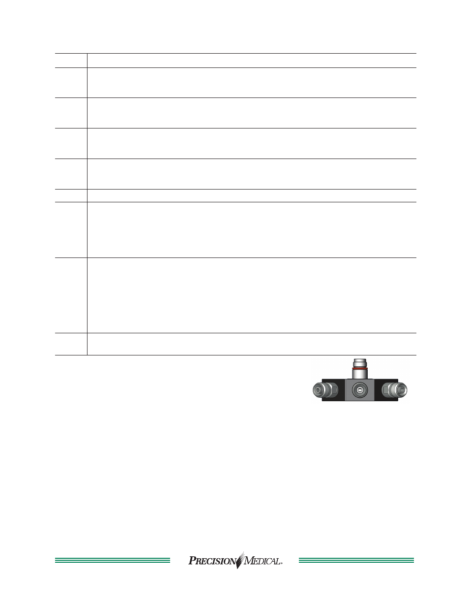
Manifold Outlet with (3) primary outlets. (Optional)
The Manifold Repair Kit (Part # 506742) is not contained
in the Blender Service Kit .
MANIFOLD ASSEMBLY SERVICE
Disassembly
1. Remove Manifold Outlet Assembly from the bottom of the Blender using a 5/32 Hex Key.
2. Unscrew (3) Primary Outlets from Manifold Block and discard.
3. Remove the Manifold Body Outlet from the bottom of the Manifold Block.
a. Remove and discard the (3) O-rings.
b. Remove and discard the plastic washer from the top of the Manifold Block.
Assembly
1. Install (3) new Primary Outlets on the Manifold Block. (Use small amount of Blue Loctite on
threads).
2. Place (3) O-rings on the Manifold Body Outlet.
3. Lubricate the hole on the Manifold Block with Krytox GPL106.
4. Insert Manifold Body Outlet through the opening of the Manifold Block.
5. Place plastic washer on top of the Manifold Body Outlet.
6. Reinstall Manifold Assembly when installing air and oxygen inlets on the Blender using a
5/32 Hex Key.