Figure 3. transient pulse window, Figure 4. trigger window, Figure 5. calibration window – KEPCO BOP VISA Driver (Universal, GPIB) User Manual
Page 5
BOP-VISA 010906
5
The BEEP button causes the power supply to beep.
The ABOUT button displays the model, serial number and firmware version number.
Running or generating a program (pattern) is accomplished by clicking the Program button on the Main
Panel (see PAR. 2.1 for details).
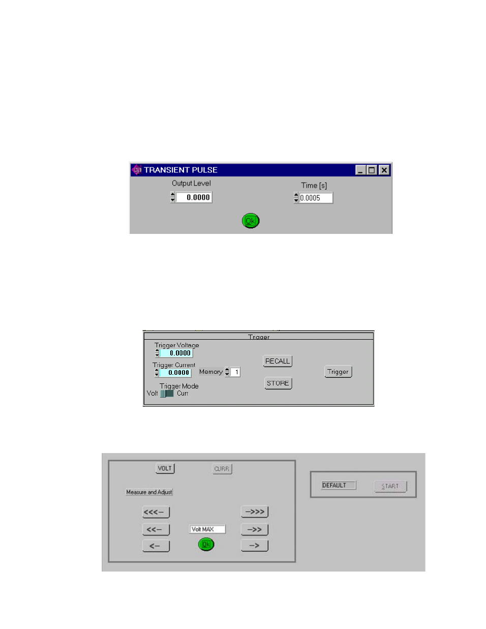
The Trans button (not available with BIT 4882 card) generates a transient pulse with the amplitude and
duration specified by the user in the Transient Pulse window (see Figure 3). The output level of the tran-
sient will either be V or A, depending on which mode is active. After the transient pulse is generated, the
output will return to the programmed values in effect before the transient was generated.
FIGURE 3. TRANSIENT PULSE WINDOW
The Trigger button opens the Trigger window (Figure 4) which allows 99 different trigger voltage and cur-
rent values, as well as mode to be stored and recalled. The STORE button stores the Trigger Mode, Trig-
ger Voltage and Trigger Current values at the selected Memory location (1-99). The Recall button displays
the Trigger Mode, Trigger Voltage and Trigger Current values stored in the selected Memory location.
Clicking the Trigger button (or double-clicking RECALL) within the Trigger window causes the power sup-
ply output to be programmed to the settings stored in the selected Memory location. .
FIGURE 4. TRIGGER WINDOW
The Calibrate button opens the Calibration Window (Figure 5), and is used to recalibrate the unit (see
Section 3 of the Operator’s Manual or Section 4 of the Service Manual).
FIGURE 5. CALIBRATION WINDOW