3 ac input requirements, Figure 2-4. conversion to 230v ac line operation, 4 cooling – KEPCO JQE 150-1.5MVPY-26956 Half Rack User Manual
Page 22: 5 preliminary operational check, Ac input requirements -4, Cooling -4, Preliminary operational check -4, Conversion to 230v ac line operation -4, R. 2.3 )
2-4
JQE SPECIAL SVC 081111
2.3
AC INPUT REQUIREMENTS
This power supply is normally supplied for operation on a single phase, nominal 115V AC line.
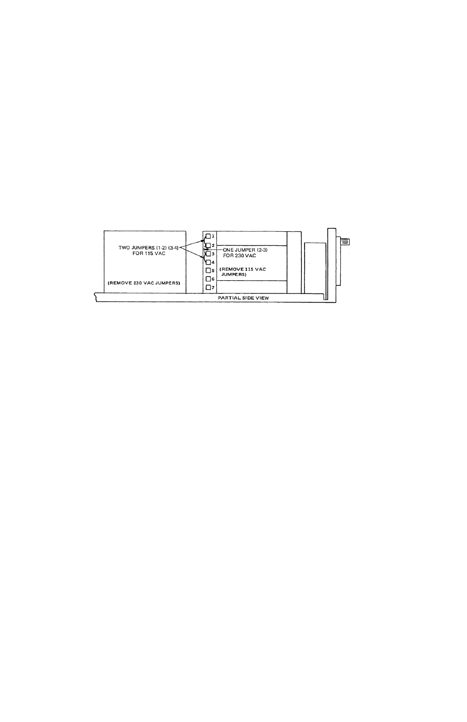
For conversion to 230V AC line operation, refer to FIG. 2-4. Remove the two wire jumpers
between transformer terminals indicated. Re-connect one (1) jumper between terminals indi-
cated. Do not change any other wiring on the transformer.
FIGURE 2-4. CONVERSION TO 230V AC LINE OPERATION
2.4
COOLING
The power transistors and rectifiers in this power supply are maintained within their operating
temperature range by means of a high efficiency heat-sink assembly, coded by an internal fan.
SIDE PANEL OPENINGS AND THE TOP OF THE CASE MUST BE KEPT CLEAR FROM
OBSTRUCTIONS TO INSURE PROPER AIR CIRCULATION. Periodic cleaning of the interior
of the power supply is recommended. If the power supply is rack mounted, or installed into con-
fined spaces, care must be taken that the ambient temperature does not rise above the limit
specified (Refer to Section 1).
2.5
PRELIMINARY OPERATIONAL CHECK
A simple operational check after unpacking and before equipment installation is advisable to
ascertain whether the power supply has suffered damage resulting from shipping. Refer to Fig-
ures 2-1 and 2-2 for location of operating controls and electrical connections.
1. Connect power supply to 115V AC line or refer to paragraph 2.3 for 230V AC operation if
required.
2. Verify that the following links are installed at the rear panel (see Figure 2-2) and that the con-
nection is tight:
TB501 between –S and –V terminals
TB501 between +S and +V terminals
TB501 between RVC and RPV1 terminals
TB502 between REF and RPC1 terminals
3. Turn CURRENT LIMIT CONTROL "A" and "B" full clockwise. Turn VOLTAGE CONTROL
fully counterclockwise.
4. Connect a DVM to terminal +S and DVM return to –S of TB501 at the rear panel.
5. Turn AC POWER circuit breaker "on." The AC PILOT LIGHT should be energized. Slowly
turn VOLTAGE CONTROL clockwise and verify the front panel voltmeter shows a gradual