2 installation, Installation -9, R. 2.6.2) – KEPCO MST Series User Manual
Page 27
MST SERIES 061813
2-9
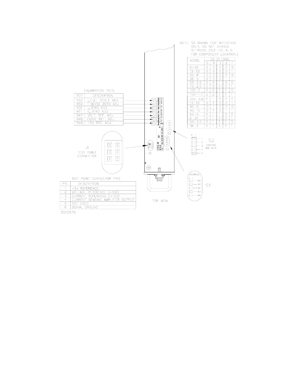
FIGURE 2-4. CONFIGURATION AND CALIBRATION CONTROLS AND TESTPOINTS
2.6.2
INSTALLATION
To install the MST Power Module in the RA 55 Rack Adapter or CA 400 case, proceed as fol-
lows:
1. The factory setting for the control bus address is 1; if address 1 is already in use, refer to
PAR. 2.6.1 to change the address setting.
NOTE: If the Power Module is already installed in a Rack Adapter and it is necessary to
change the control bus address, the Power Module must first be removed from the
Rack Adapter as described in PAR. 2.6.3 below.
2. To ensure full engagement of the module interconnect to the RA 55 Rack Adapter or CA 400
case, pull out the two slotted captive thumb screws (at the front of the Module) and turn
counterclockwise until the threads engage.