1 parallel current share - internal dip switches, Parallel current share - internal dip switches -9, S 2-5 – KEPCO RA 19-3B User Manual
Page 25: Ar 2.4.2.2.1)
RA 19-3B 011409
2-9
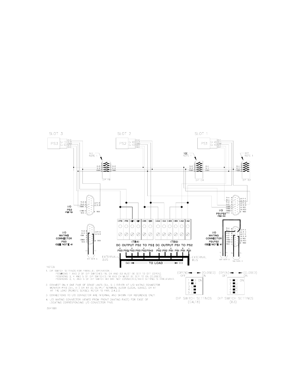
2.4.2.2.1 PARALLEL CURRENT SHARE - INTERNAL DIP SWITCHES
To configure adjacent slots, use the internal DIP switches to connect the Current Share bus.
Using internal DIP switches permits only adjacent power supplies be connected in parallel.(i.e.,
PS1/PS2, PS2/PS3 and PS1/PS2/PS3). PS1 and PS3 cannot be configured in parallel using
internal DIP switches without including PS2 as well. Contact Kepco Applications Engineering for
non-standard configurations using internal DIP switches.
To connect the current share lines locate DIP switches C4 and F8 (see Figure 2-1) and set posi-
tion 3, 4, 5 to ON (closed). For example to connect PS1, PS2 and PS3 in parallel, set DIP
switches F8 and C4, position 3, 4, 5, to ON (closed) (see Figure 2-5); set DIP switch B3, posi-
tions 1 through 5 to OFF (open) (positions 1-2 of B3 must be OFF for parallel configurations and
positions 3-5 are not connected.
NOTE: If internal DIP switch positions 3, 4 are closed (ON), use only one pair of sense
lines to monitor voltage.
FIGURE 2-5. PARALLEL OUTPUTS USING INTERNAL DIP SWITCHES TO PARALLEL SENSE
LINES AND CURRENT SHARE, PS1, PS2 AND PS3 (TYPICAL), SIMPLIFIED DIAGRAM