Displays, And-tft-5vx-kit – Purdy AND-TFT-5VX-KIT User Manual
Page 4
AND-TFT-5VX-KIT
Displays
Purdy Electronics Corporation • 720 Palomar Avenue • Sunnyvale, CA 94085
05/13/03
Tel: 408.523.8200 • Fax: 408.733.1287 • [email protected] • www.purdyelectronics.com
4
CN 1
Pin #.
Symbol
I/O
Function
Remark
1
DIO1
I/O
Horizontal Start Pulse Signal Input or Output
Note 1
2
VSS1
I
Ground
3
VDD1
I
Power Supply for Source
4
CLK
I
Horizontal Shift Clock)
5
VSS1
I
Ground
6
R/L
I
Up/Down selection
Note 2
7
R0
I
Red Data (LSB)
8
R1
I
Red Data
9
R2
I
Red Data
10
R3
I
Red Data
11
R4
I
Red Data
12
R5
I
Red Data (MSB)
13
Vss1
I
Ground
14
G0
I
Green Data (LSB)
15
G1
I
Green Data
16
G2
I
Green Data
17
G3
I
Green Data
18
G4
I
Green Data
19
G5
I
Green Data (MSB)
20
VSS1
I
Ground
21
B0
I
Blue Data (LSB)
22
B1
I
Blue Data
23
B2
I
Blue Data
24
B3
I
Blue Data
25
B4
I
Blue Data
26
B5
I
Blue Data (MSB)
27
LD
I
Load output signal
Note 3
28
REV
I
Data invert control
Note 4
29
POL
I
Polarity
Note 5
30
DIO2
I/O
Horizontal Start Pulse Signal Input or Output
Note 6
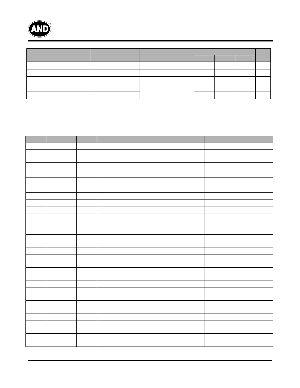
Recommended Operating Conditions (Driving for Backlight) Ta = 25°C
Note 1: The wave form of lamp driving voltage should be as close to a perfect SIN wave as possible
Note 2: This value is not output voltage of inverter. The voltage of inverter must be larger than the starting voltage.
Item
Symbol
Remark
Specifications
Unit
Min.
Typ.
Max.
Lamp Voltage
V
L
I
L
= 5 mA
432
480
528
Vrms
Lamp Current
I
L
–
4.5
5.0
5.5
mA
Lamp Frequency
P
L
Note 1
40
43
80
KHz
Kick-Off Voltage (25 °C)
V
S
Note 2
–
–
600
Vrms
Kick-Off Voltage (0 °C)
V
S
–
–
800
Vrms
Input / Output Terminals:
TFT-LCD Panel Driving