Diode test, Current measurement – Amprobe DM7C Digital-Multimeter User Manual
Page 9
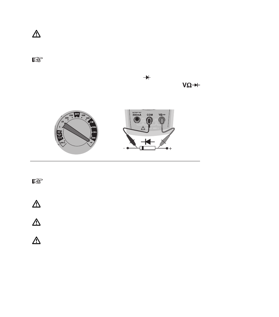
Diode Test
Prior to any diode test, it must be ensured, that the diode to be tested does not
have voltage across it. Failure to comply with this prescription can lead to dan-
gerous user injuries or cause instrument damage. Additionally, foreign
voltages falsify the measurement result.
Resistors and semiconductor paths in parallel to the diode cause falsified meas-
urement results.
1) Position measurement function selection switch to
measurement range.
2) Connect the black test lead to the COM socket and the red test lead to the
socket.
3) Connect test leads to UUT.
4) Read the measurement result displayed on the screen.
Current Measurement
Ensure that the measurement circuit is not live when connecting the
measurement instrument.
The instruments may only be used in current circuits protected at 16 A up to a
nominal voltage of 600 V.
The nominal cross section of connecting line has to be respected and a safe con-
nection has to be ensured.
After instrument fuse tripping eliminate the cause for the tripping prior to fuse re-
placement.
7