Amprobe MO-100 Milliohm-Meter User Manual
Page 17
13
FUSES REPLACEMENT
The maximum continuous voltage which can be applied across the potential
and current leads is around 10.7V. Applying more than that voltage will
automatically blow their respective fuses.
However, the crowbar trigger can be factory adjusted for your application.
We have specially selected that method to stop damaging the instrument,
should it be misused
There are three fuses:
• Power Supply Fuse
The power supply fuse is situated under the tester. Open the battery
compartment, and replace the fuse with the same type
(0.5 A, >24V, Slow Blow)
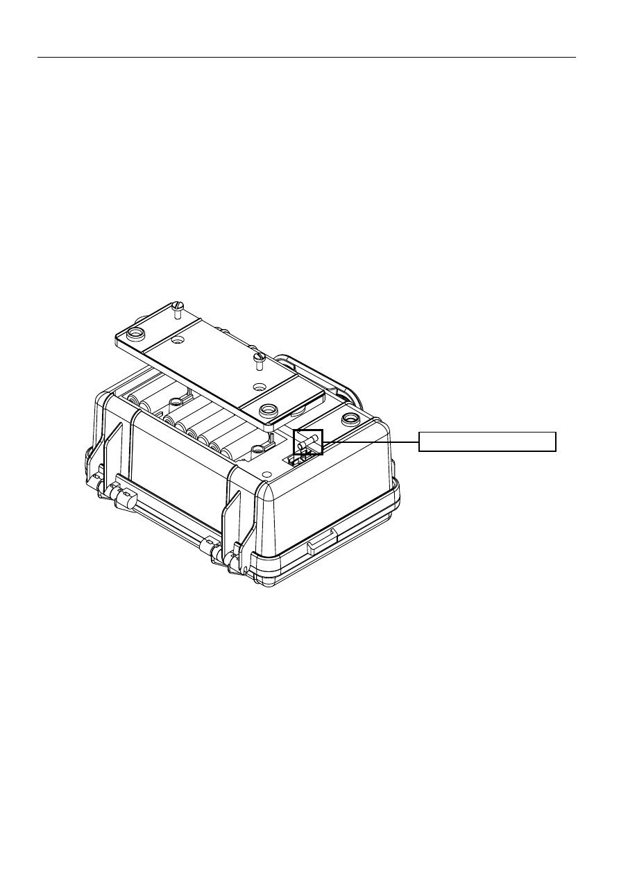
• Current Circuit Fuse
Fuse protection is provided on the current terminals. This fuse is situated
under the Printed Circuit Board. To access it, you need to unscrew the
four mounting screws which are holding the font panel. Two os these
screws are located under the foots, and the two others are located inside
the battery compartment.
The fuse is automatically blow by the crowbar, should voltage be
present on the resistance under test. This is to prevent damage to the
instrument. It is indicative of this fuse being blown is the RC Led stays
“on”. (HBC, 0.5 A, 250Vac, Slow Blow)
Fuses (0.5A / 250V)