3 lsisas9211-4i hba characteristics, 1 memory, 2 leds – Avago Technologies SAS 9200-8e Host Bus Adapter User Manual
Page 13: 3 connectors, Lsisas9211-4i hba characteristics
LSI Corporation
- 13 -
PCI Express to 6Gb/s Serial Attached SCSI (SAS) Host Bus Adapters User Guide
May 2013
Host Bus Adapter Characteristics
Characteristics of the LSI 6Gb/s HBAs
3.1.3
LSISAS9211-4i HBA Characteristics
3.1.3.1
Memory
The LSISAS9211-4i HBA provides one 4-M × 8-bit Flash ROM for storing the firmware and BIOS. The LSISAS9211-4i HBA
can provide up to 32 K × 8-bit NVSRAM for storing nonvolatile RAID information when a system failure occurs.
3.1.3.2
LEDs
The LSISAS9211-4i HBA has a 4-pin header for connection of activity LEDs. The header connects to two LEDs (see
), which indicate SAS activity on port 0 and port 1.
3.1.3.3
Connectors
This section describes the different connectors on the LSISAS9211-4i HBA. See
PCIe Connector (J1). The LSISAS9211-4i HBA supports a x4 interface. The PCIe host interface connection is through
the edge connector, J1, which provides connections on both the top (J1B) and bottom (J1A) of the board. The signal
definitions and pin numbers conform to the PCIe specifications.
SAS/SATA Connector (J7). The LSISAS9211-4i HBA supports SAS connections through connector J7, which is an
SFF-8087 mini-SAS, internal, right-angle connector.
Activity LED Header (J3). The LSISAS9211-4i HBA has a 4-pin, right-angle, 0.1-in. pitch header for driving external
activity LEDs.
UART Connector (J5). The UART connector debug port requires a special cable and LSI support to gather detailed
IOC status.
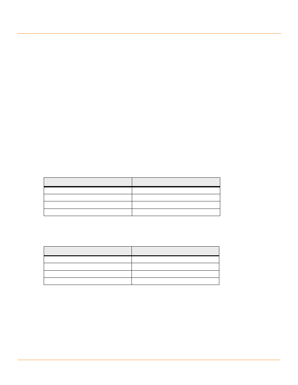
Table 8 LSISAS9211-4i LED Header
Pin
Function
1
3.3 V
2
Port 0
3
Port 0
4
3.3 V
Table 9 LSISAS9211-4i UART Pinout
Pin
Function
1
UART0_TX
2
Gnd
3
UART0_RX
4
3.3 V