Schematic diagram, The output lines, Input output – Avago Technologies ASSR-1411-001E User Manual
Page 2
Advertising
2
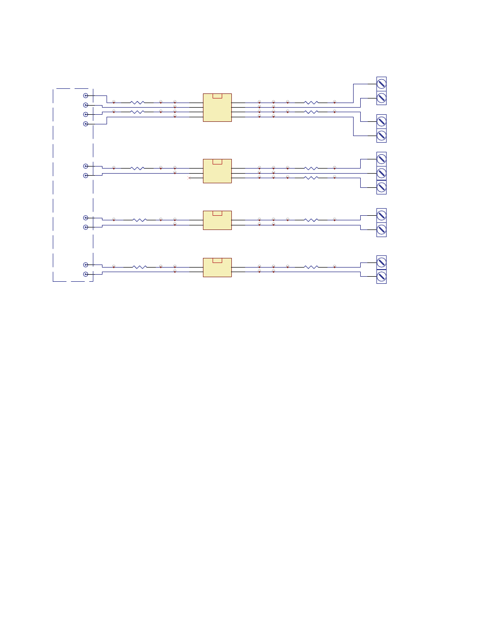
Schematic Diagram
2
2
3
3
4
4
1
1
5
5
6
6
7
7
8
8
U1
DIP 8PIN
Gull Wing SMT
2
2
3
3
1
1
4
4
5
5
6
6
U2
DIP 6PIN
Gull Wing SMT
2
2
1
1
3
3
4
4
U3
SOP 4PIN
2
2
1
1
3
3
4
4
U4
SSOP 4PIN
R4
R3
R1
R2
R5
R8
R10
R11
R9
R7
R6
TP1
TP2
TP3
TP4
TP5
TP6
TP9
TP10
TP11
TP12
TP13
TP14
TP15
TP16
TP17
TP18
TP19
TP20
TP33
TP34
TP44
TP54
TP25
TP26
TP27
TP28
TP29
TP30
TP31
TP32
TP39
TP40
TP41
TP42
TP43
TP21
TP22
TP23
TP24
TP8
TP7
TP35
TP36
TP37
TP38
TP45
TP46
TP47
TP48
J2
CATHODE-A
J3
ANODE-B
J1
ANODE-A
J4
CATHODE-B
J6
CATHODE-C
J5
ANODE-C
J8
CATHODE-D
J7
ANODE-D
J10
CATHODE-E
J9
ANODE-E
TP49
TP50
TP51
TP52
TP53
INPUT
OUTPUT
INPUT PIN
1
2
A
SCREW-2PIN
1
2
B
SCREW-2PIN
1
2
3
C
SCREW-3PIN
1
2
D
SCREW-2PIN
1
2
E
SCREW-2PIN
The output lines
to the screw terminals are
50ohms lines, which can withstand 6A, 300Vac.
Advertising
This manual is related to the following products: