Pinout table operation – Avago Technologies ASSR-1411-001E User Manual
Page 5
5
Pinout Table
Operation
In the schematic diagram, R
1
, R
2
,R5, R8 and R10 are
the current limiting resistors before the input pins. If
the LED is driven by a 5V power supply, a 680 ohm
resistor can be used. In the schematic diagram, R
3
,R
4
,
R6, R7, R9 and R11 are the load. The impedance of the
load should be sufficient enough to limit the output
current to less than the recommended maximum
output current.
When the LED is on (or power is applied to the LED),
the SSR (MOSFET) turns on, current will flow through
the load. When the LED is off (or there is no power
applied to the LED), the SSR (MOSFET) turns off, there
is no current flowing through the load.
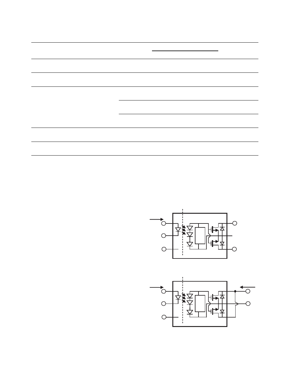
For the operation of U2, the ASSR-xx1x-001E Series is
packaged in a 6-Pin DIP with Gull Wing Surface Mount,
but only five pins are used. Pins 1 and 2 are the anode
and the cathode of the input LED, respectively, and
Pin 3 is not connected (N.C.) internally. Pins 4, 5, and 6,
at the output side can be configured as either
Connection A or Connection B as shown in figure 3.
With Connection A as shown in figure 3a, the signal at
the output of the SSR can have either positive or
negative polarity. This means that the ASSR Series can
pass either ac or dc signals. With Connection B, the
signal at the output of the ASSR must have its polarity
as indicated in figure 3b. In this configuration, pins 4
and 6 are tied together, and the ASSR can control dc
signals only. The advantage of using Connection B is
that it places two output MOSFETs in parallel with each
other, rather than in series. This configuration reduces
Channel
Description
Input Current
Output
Load Conditions
1
2
3
A
U1, Gullwing Surface Mount
8-Pin, ASSR-xx2x-002E
5mA nominal,
20mA max.
AC or DC
Power
AC or DC
load
N.A.
Refer to product
datasheet
B
U1, Gullwing Surface Mount
8-Pin, ASSR-xx2x-002E
5mA nominal,
20mA max.
AC or DC
Power
AC or DC
load
N.A.
Refer to product
datasheet
C
U2, Gullwing Surface Mount
6-Pin, ASSR-xx1x-001E
5mA nominal,
20mA max.
AC or DC
Power
N.C.
AC or
DC load
Refer to product
datasheet
5mA nominal,
20mA max.
DC Power DC load
N.C.
Refer to product
datasheet
5mA nominal,
20mA max.
DC Power DC load
DC
Power
Refer to product
datasheet
D
U3, Small Outline 4-Pin,
ASSR-xx1x-003E
5mA nominal,
20mA max.
AC or DC
Power
AC or DC
load
N.A.
Refer to product
datasheet
E
U4, Shrink Small Outline
4-Pin, ASSR-xx1x-006E
5mA nominal,
20mA max.
AC or DC
Power
AC or DC
load
N.A.
Refer to product
datasheet
the output on-resistance of the ASSR significantly and
increases its output current capability by a factor of
two. Figure 3 also defines the polarity for the input
side of the ASSR.
Figure 3a - Connection A (AC or DC)
Figure 3b - Connection B (DC only)
Opto-isolation
Tu
rn-
o
ff
Ci
rc
ui
t
1
2
3
6
5
4
V
F
N.C.
+
-
I
F
Opto-isolation
Tu
rn-
o
ff
Ci
rc
ui
t
1
2
3
6
5
4
V
F
N.C.
+
-
I
F
I
O
V
O
+
-
+
-
-