Rear panel – Roland V-800HD MKII Multi-Format Video Switcher User Manual
Page 16
16
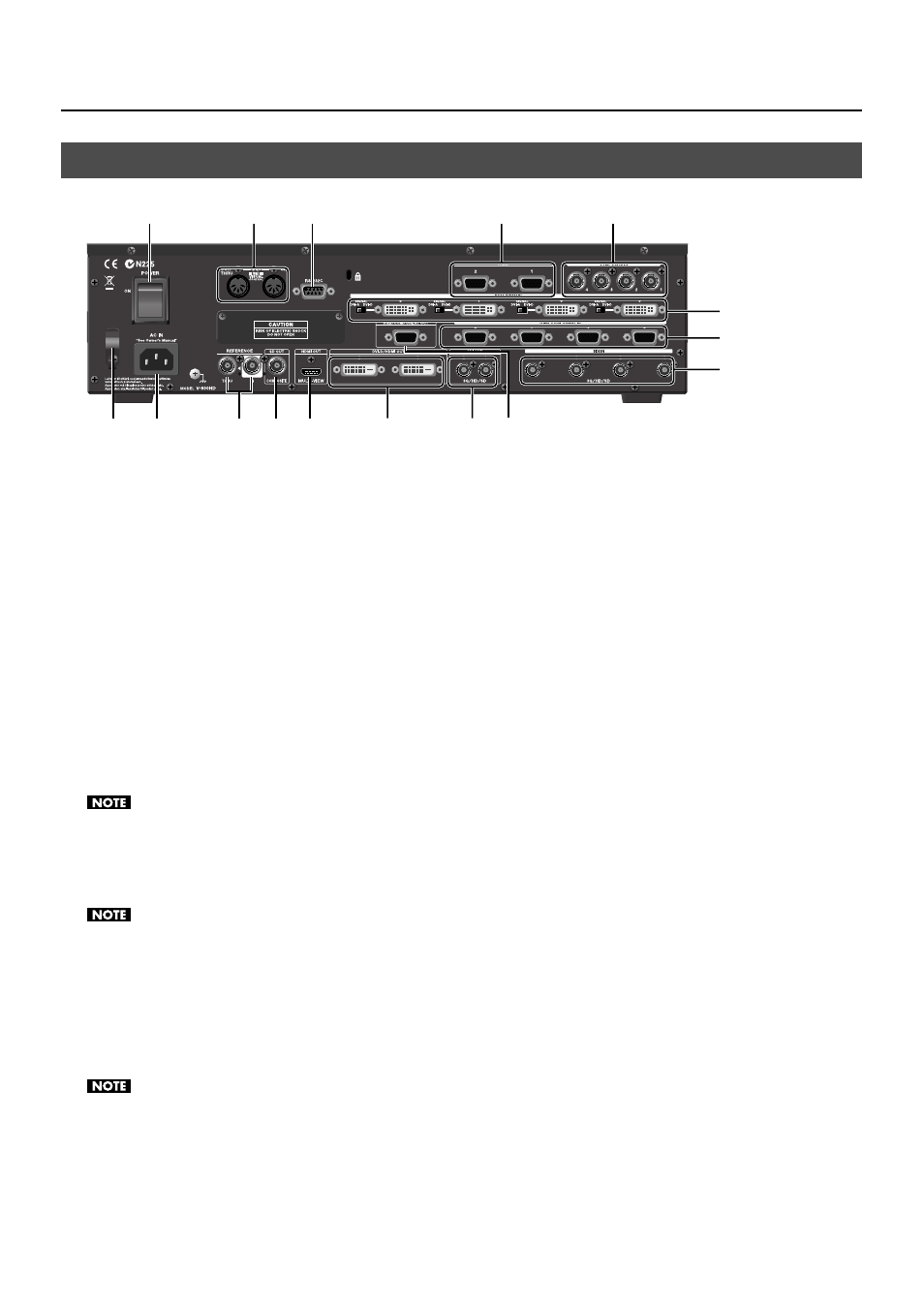
Part Names and Functions
fig.rear-panel.eps
1 POWER
Switch
This turns the power to the V-800HD on and off.
2
MIDI IN and OUT/THRU Connectors
You can use these when you remote control the unit from an external MIDI device (a device compatible with MIDI VISUAL
CONTROL or the like), or when using the unit to perform remote control of another device.
3 RS-232C
Connector
You can use this when you remote control the unit from an external RS-232C device.
* For information about operating the unit remotely via MIDI or the RS-232C interface, download the “Remote Control Guide” from the following
Roland website.
http://www.rolandsystemsgroup.net/
4 TALLY
Connectors
Connect devices provided with tally-light feature (p. 25).
5
COMPOSITE IN Connectors
Connect video cameras or other equipment capable of composite output. Composite inputs are assigned to channels 1 through 4.
By default, SDI IN 1 through 4 are selected as the sources for channels 1 through 4. To enable composite input, use the menus to change the
source. Refer to “Making a Composite Connection” (p. 20).
6
DVI-I/HDMI IN Connectors
Connect a computer or other source equipment capable of DVI output. DVI input is assigned to channels 5 through 8.
Use the switches to select [DVI-A] or [DVI-D] as required to match the type of output signal from the source equipment. Refer to “Making a DVI/
7
RGB/COMPONENT IN Connectors
At RGB/COMPONENT IN, connect a computer or other source equipment capable of analog RGB output. RGB inputs are assigned
to channels 5 through 8.
* By using a conversion cable from component to mini D-Sub 15-pin type, you can also connect equipment capable of Y/Pb/Pr component
output.
By default, DVI-I/HDMI IN 5 through 8 are selected as the sources for channels 5 through 8. To enable RGB input, use the menus to change the
source. Refer to “Making an RGB/Component Connection” (p. 22).
8
SDI IN Connectors
Connect video cameras or other source equipment capable of SDI output. SDI inputs are assigned to channels 1 through 4.
* As SDI source equipment, you can connect devices that output 3G-SDI, HD-SDI or SD-SDI signals.
Rear Panel
1
2
3
4
5
6
7
8
9
10
11
12 13
14
15
16