Front – Sony LHP-1 Lens Hood User Manual
Page 11
1. Overview: Location and Function of Parts
11
11.
AUDIO IN connector (XLR 5-pin)
Input external microphone or audio
equipment signals.
When the audio source is set to LINE or MIC
using the AUDIO IN switch, this connector
functions as an AUDIO IN CH-1 and AUDIO IN
CH-2 connector.
When the audio source is set to AES/EBU
using the AUDIO IN switch, this connector
functions as the AUDIO IN CH-1/2 and AUDIO
IN CH-3/4 connector.
12.
BACK button
Cancels the menu setting and moves up one
level in the menu hierarchy during menu
display. Cancels the execution process or
pending process during process execution/
pending display (pages 38, 54, 64).
13.
LOCK switch
Locks the operation of the buttons on the
Assistant side. When locked, the switch
background LED lights in orange.
14.
ACCESS (SD card access) lamp
(page 34)
15.
REC ACTIVE lamp
The lamp is lit green when the REC button is
enabled.
16.
REC (recording start/stop) button/lamp
Press to start recording, turning the REC lamp
on. Press again to stop recording, turning the
REC lamp off (page 107).
The REC lamp flashes when a device error or
warning occurs.
17.
CLIPS button
Press to display the clip list screen on the sub
display to enable clip operations (page 93).
Simultaneously, the clip screen is displayed on
the mini display.
To switch from playback mode to shooting
mode, press the HOME button.
18.
USER button
Press to display the user function list on the
sub display, and to operate the ITEM keys 1 to
5 user function buttons.
ITEM key 6 is the user function list EDIT button.
Press this button to display the function
selection screen for the user function buttons
and assignable buttons. Press again when the
user functions screen is displayed to return to
the previous display (page 48).
19.
Internal microphone
Use to record audio.
Select the input channel for the internal
microphone using Audio > Audio Input >
Internal Mic Select (page 84) in the full
menu.
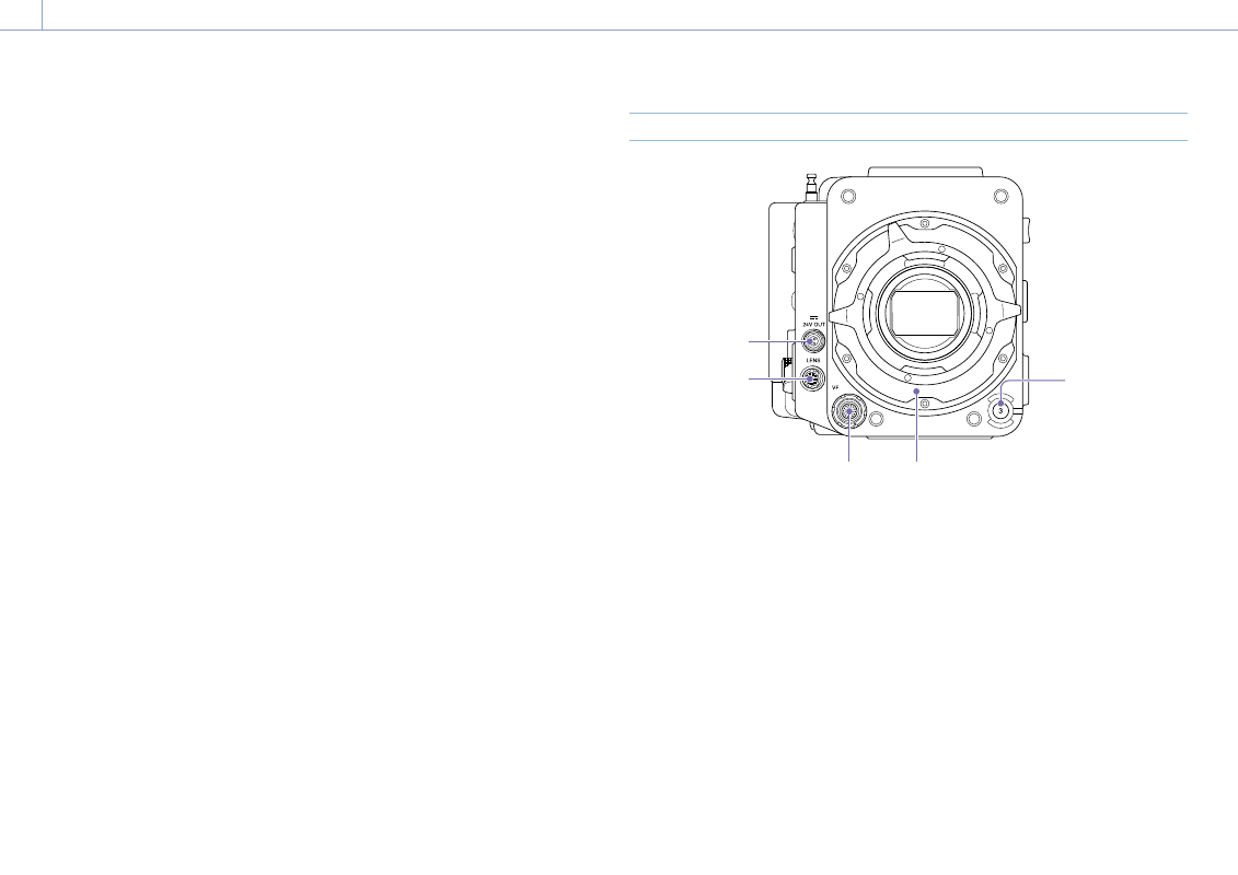
Front
1
2
3
4
5
1.
ASSIGN (assignable) button 3 (page 48)
Assign functions using the EDIT page of the
user functions screen (page 48).
The assigned function toggles between on/off
(enabled/disabled) or is activated with each
press.
2.
PL lens mount adaptor (page 21)
3.
VF (viewfinder output) connector
(page 24)
4.
LENS connector (12-pin)
Supports iris, focus, and zoom control from a
network-connected computer, smartphone, or
tablet.
5.
24V OUT connector (24 V DC output,
Fischer 3-pin)
24 V DC power supply output connector
(page 120).
The output voltage and maximum output
current of this connector vary depending on
the input voltage to the unit. The maximum
current includes the output current from
the 24V OUT connector on the rear panel
(page 12).
11 V to 17 V input
Output voltage: 24 V
Maximum output current: 1.0 A
22 V to 32 V input
Output voltage: Same as the input voltage
Maximum output current: 2.0 A