Rolls MU118 Digital Multimeter User Manual
Rolls digital multimeter mu118 operation manual
ROLLS DIGITAL MULTIMETER
MU118 OPERATION MANUAL
1. INTRODUCTION
This instrument is compact, rugged, battery operated, handheld 3
1
/2 digit digital multimeter for measuring DC and AC voltage, DC
and AC current, resistance and diode, capacitance, transistor,
continuity test, temperature and frequency.
The dual–slope A-D converter uses C-MOS technology for
auto-zeroing, polarity selection and over-range indication. Full
overload protection is provided. It is an ideal instrument for use in
the field, laboratory, workshop, hobby and home applications.
2. FEATURES
* Push-button ON-OFF power switch.
* Single 30 position easy to use rotary switch for function and range
selection.
* High sensitivity of 100µV.
* Automatic over range indication with the “1” displayed.
* Automatic polarity indication on DC range.
* All ranges fully protected.
* Resistance measurements 0.1
Ω
to 200M
Ω
.
* Capacitance measurements 1pF to 20µF.
* Diode testing with 1mA fixed current.
* Transistor hFE test with Ib
≈
100µA.
* Temperature measurement with or without K type thermocouple.
3. SPECIFICATIONS
Accuracies are ± (% reading + No. of digits)
Operating environment: 23±5
℃
, less than 75% R.H.
DC Voltage
Range
Accuracy
Resolution
200mV
±(0.5% of rdg + 3d)
100
μ
V
2V
1mV
20V
10mV
200V
100mV
1000V
±(0.8% of rdg + 3d)
1V
Input impedance: 10M ohm on all ranges.
Overload Protection: 1000V DC or peak AC on all ranges.
AC Voltage
Range
Accuracy
Resolution
2V
±(0.8% of rdg + 3d)
1mV
20V
10mV
200V
100mV
750V
±(1.2% of rdg + 5d)
1V
Input impedance: 10M
Ω
on all ranges
Frequency range: 40Hz to 400Hz.
Overload protection: 700V rms or 1000V peak continuous on ac
ranges, except 200mV ac range (15 seconds maximum above
300V rms).
Indication: Average (rms of sine wave)
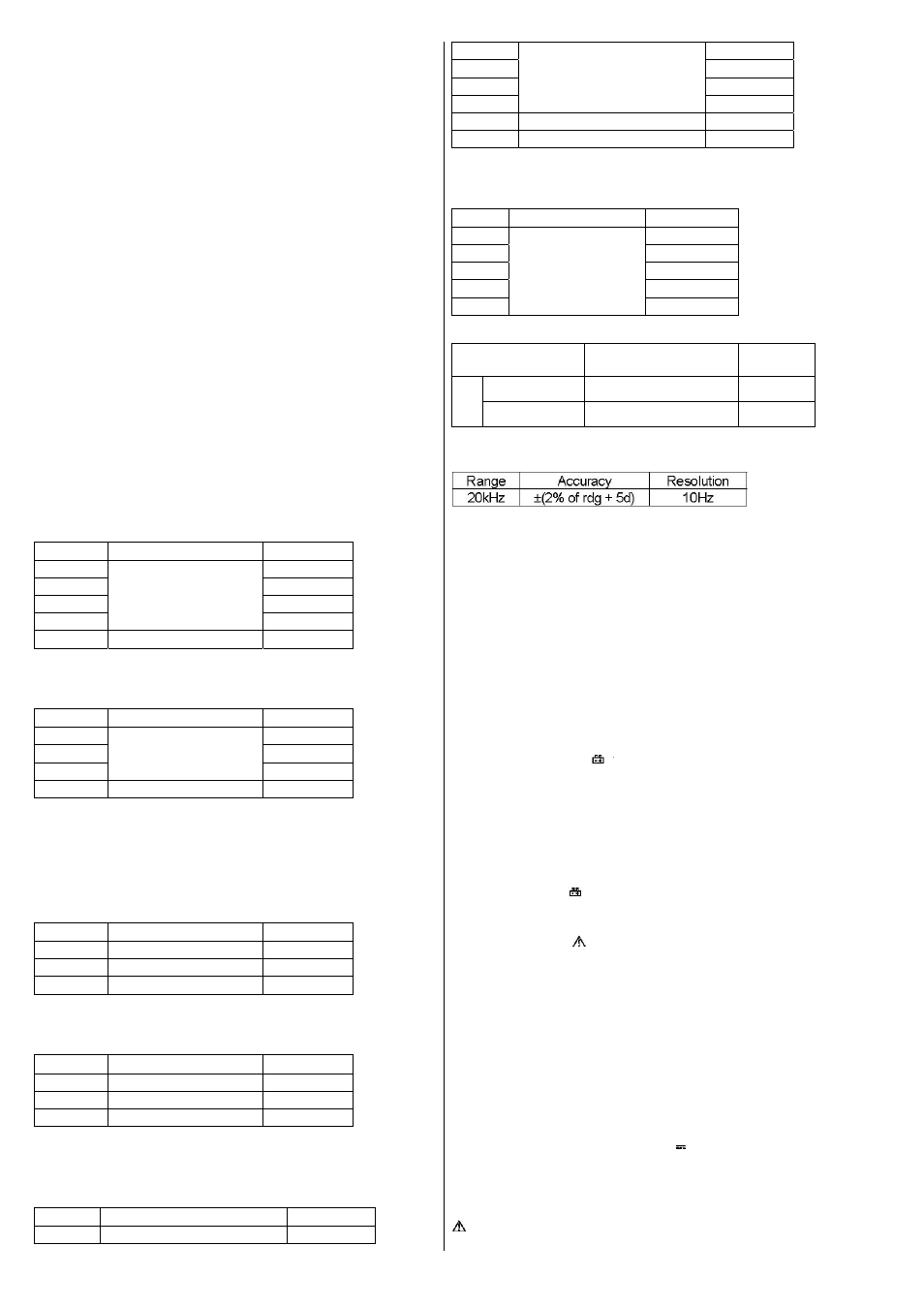
DC Current
Range
Accuracy
Resolution
20mA
±(0.8% of rdg + 2d)
10
μ
A
200mA
±(1.2% of rdg + 2d)
100
μ
A
10A
±(2% of rdg + 5d)
10mA
Overload protection: 0.2A/250V fuse. (20A range not fused)
Maximum input current: 20A, 15 sec. max.
AC Current
Range
Accuracy
Resolution
20mA
±(1% of rdg + 3d)
10
μ
A
200mA
±(1.8% of rdg + 3d)
100
μ
A
10A
±(3% of rdg + 7d)
10mA
Overload protection: 0.2A/250V fuse. (20A range not fused.)
Frequency range: 40Hz to 400Hz.
Maximum input current: 10A, 15 sec. max.
Indication: Average (rms of sine wave)
Resistance
Range Accuracy
Resolution
200
Ω
±0.8% of rdg ± 3d
0.1
Ω
2k
Ω
±0.8% of rdg ± 2d
1
Ω
20k
Ω
10
Ω
200k
Ω
100
Ω
2M
Ω
1k
Ω
20M
Ω
±1% of rdg ± 5d
10k
Ω
200M
Ω
±[5% of (rdg -1M
Ω
) +10d]
10k
Ω
On 200M
Ω
range, if short the two test leads, display reading is 10
digits should be subtracted from measurement results.
Capacitance
Range Accuracy
Resolution
2nF
±(3% of rdg + 5d)
1pF
20nF
10pF
200nF 100pF
2µF
1nF
20µF
10nF
Temperature
Range
Accuracy
Resolutio
n
℃
-50~400
℃
±(1.2% of rdg + 4d)
1
℃
400~1000
℃
±(1.9% of rdg + 15d)
1
℃
*Using K type thermocouple probe.
Frequency Test
Overload protection: AC 220V rms.
4.
GENERAL CHARACTERISTICS
Maximum display: 1999 counts (3
1
/2 digits) with automatic polarity
indication and eng. unit.
Indication method: LCD display.
Measuring method: Dual-slope integration A-D converter system.
Overrange indication: “1” or “-1” figure only in the display.
Maximum common mode voltage: 500V DC/AC rms.
Reading rate: 2~3 reading per sec. (approximate).
Temperature for guaranteed accuracy: 23±5
℃
.
Temperature ranges: Operating: 0
℃
to 40
℃
(32
℉
to 104
℉
)
Storage: -10
℃
to 50
℃
(14
℉
to 122
℉
)
Power supply: One 9V battery (NEDA 1604 or 6F22 or equivalent).
Low battery indication:
to lift of display.
Size: 88 (W) × 170 (D) × 38(H) mm.
Weight: 340g (including battery)
Accessories: Operating manual, set of test leads and thermocouple
(K type, 300
℃
)
5.
OPERATION
1. Check the 9-volt battery by setting the ON-OFF switch to ON. If the
battery is weak, a
sign will appear on the display. It is does not
appear on the display, proceed as below. See maintenance if the
battery has to be replaced.
2. The mark or sign
next to the test lead jacks is for warning that
the input voltage or current should not exceed the indicated
values. This is to prevent damage to the internal circuit.
3. The function switch should be set to the range which you want to
test before operation.
4. If the voltage or current range is not known beforehand set the
function switch to a high range and work down.
5. When only the figure “1” is displayed, over-range is being indicated
and the function switch must be set to a higher range.
5.1) DC Voltage Measurement
1, Connect the BLACK test lead to the COM jack and the RED test
lead to the V/
Ω
jack.
2. Set the FUNCTION switch to the “V
range to be used and
connect the test leads across the source or load under
measurement. The polarity of the RED lead connection will be
indicated at the same time as the voltage.
”
NOTE:
Do not apply more than 1000V to the input, Indication is
possible at higher voltages but there is danger of damaging the