Pa1594, Testing a straight-through cable, Testing a crossover cable – Tempo PA1594 LAN and A/V Cable-Check Tester User Manual
Page 3: Testing coaxial cable, Specifications, Maintenance
PA1594
3
TEMPO COMMUNICATIONS
1390 Aspen Way • Vista, Ca 92081 USA • 800-642-2155
Testing a Straight-through Cable
Test Mode
1. Connect the Main unit to one end of the cable to be tested and the Remote unit
to the other end of this cable.
2. Set the mode selector switch to the
Standard
position.
3. Press the
TEST
button and then release it. The tester starts testing the cable.
The five green LEDs flash one time sequentially from top to bottom, and then the
tester shows the test result—flashing LED indicates this pair has a fault while
fault indicator LED lights up to indicate the type of fault.
4. The test lasts about 12 seconds, and then the tester turns off automatically.
Press the
TEST
button to stop the test manually at any time. Pressing the
TEST
button turns the tester off.
Example for Test mode: The cable fault is a SHORT on pair 1-2 and pair 3-6.
After the five green LEDs flash one time sequentially from top to bottom, the tester
displays the following test results simultaneously:
• Pair 1-2 LED and pair 3-6 LED flash green while the SHORT LED lights red.
• Pair 4-5 LED lights green indicating a good pair.
• Pair 7-8 LED lights green indicating a good pair.
Debug Mode
The Debug mode identifies which cable pairs have a wiring fault. The unit cycles
through pairs, displaying a test result one pair at a time. A fault is indicated by
simultaneously lighting a pair of LEDs and the fault indicator.
1. Set the mode selector switch to the
Standard
position. Then press and hold the
TEST
button until all LEDs light; release the button.
2. The pair LEDs and the fault indicator LEDs work together to identify which pair is
incorrect.
a. If a pair LED flashes two times in series (one short and one long) while no
fault indicator LED lights, the pair is wired correctly.
b. If a pair has fault(s), its pair LED will give a short flash. Then this pair LED,
other pair LEDs related to this pair’s fault(s), and the fault indicator LED(s) will
give a long flash simultaneously.
c. If a pair LED gives only a short flash that is not followed by a long flash, this
pair has an OPEN fault.
3. After the Debug function cycles four times through the pairs, the tester turns
off automatically. Press the
TEST
button to stop the test manually at any time.
Pressing the
TEST
button turns the tester off.
Example for Debug mode: The cable fault is a SHORT on pair 1-2 and pair 3-6.
The Debug mode LED series will be as follows:
• Pair 1-2 LED gives a short flash and then pair 1-2 LED, pair 3-6 LED, and the
SHORT red LED give a long flash simultaneously.
• Pair 3-6 LED gives a short flash and then pair 3-6 LED, pair 1-2 LED, and the
SHORT red LED give a long flash simultaneously.
• Pair 4-5 LED flashes two times in series while no fault indicator LED lights. This
indicates that this pair is wired correctly.
• Pair 7-8 LED flashes two times in series while no fault indicator LED lights. This
indicates that this pair is wired correctly.
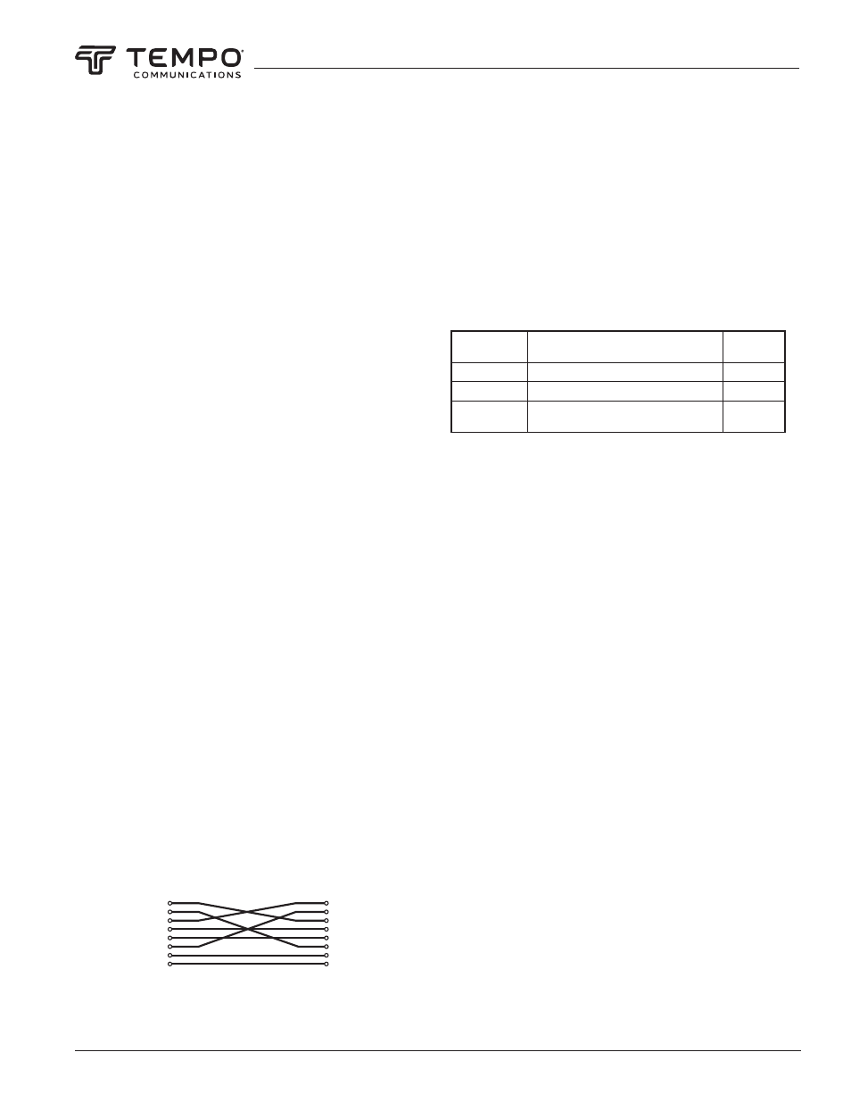
Testing a Crossover Cable
The method of testing crossover cable is almost the same as testing straight-through
cable. The only difference is that the mode selector switch is in
Cross Cable
position
to test crossover cable instead of the
Standard
position for straight-through cable.
Refer to the “Testing a Straight-through Cable” section and set the mode selector
switch to the
Cross Cable
position to test crossover cable.
1
2
3
4
5
6
7
8
1
2
3
4
5
6
7
8
Crossover Cable Wiring
Testing Coaxial Cable
Note: For coaxial cable tests, the mode selector switch can be in any function
position.
1. Connect one end of the coaxial cable to be tested to the BNC socket of the Main
unit and the other end of the coaxial cable to the BNC socket of the Remote unit.
Note: The terminators on the cable to be tested should match the BNC sockets
of the tester.
2. Press the
TEST
button and then release it. The five green LEDs of the Main unit
will flash one time sequentially from top to bottom, and then the tester shows the
test result:
• If the SHIELD/COAX LED lights green, the coaxial cable has no fault.
• If the SHIELD/COAX LED does not light, the cable is faulty.
Note: Refer to “Testing Examples” on the last page of this manual for reference on
how to test the continuity of RCA, BNC, and Cable TV “F” cables.
Indicator Light
Illuminated
Result
Resistance
PASS
Good continuity
40-100 Ω
SHORT
Cable is shorted
< 40 Ω
OPEN
Cable is broken, bad shield connector, or
bad center conductor connection
> 100 Ω
Specifications
Cable Length:
Minimum: 1 m (3 ft)
Maximum: 300 m (900 ft)
Battery: 2 x 1.5 V AAA
Size:
Master Unit: 96.8 x 58.2 x 32.8 mm (3.81 x 2.29 x 1.29 in)
Remote Unit: 96.8 x 58.2 x 32.8 mm (3.81 x 2.29 x 1.29 in)
Weight: Approximately 165 g (5.8 oz)
Maintenance
Battery Replacement
When the LOW BATT LED lights continuously, the batteries are low and should be
replaced immediately.
1. Remove the screws on the back cover of the Main unit and remove the back
cover.
2. Replace the old batteries with new ones (observe polarity).
3. Reinstall the back cover and the screws.