Whirlwind MCT7 - Multi Connector Cable Tester User Manual
Page 3
2. Plug the other end of the lead into the corresponding connector on the
OUTPUT (right) side of the unit.
3. Turn the Pin Selector Switch to position 1 to verify continuity of pin 1 of the
INPUT connector.
4. At least one pair of LEDs should light at the same time to show continuity
between INPUT and OUTPUT pins. Remember the five YELLOW LEDs on the bottom
row show the INPUT pin and only one will light in any position of the Pin Selector
switch. The five GREEN LEDs on the top row indicate continuity to the OUTPUT pins
of the cable being tested. More than one of these five LEDs may illuminate. To determine
which position of the Pin Selector Switch corresponds to the pins of the selected
connector refer to Table 1 or the diagrams printed on the front panel of the MCT-7 Cable
Tester.
5. Rotate the Pin Selector Switch to position 2, 3 and so on, until all pins of the
selected connectors have been tested.
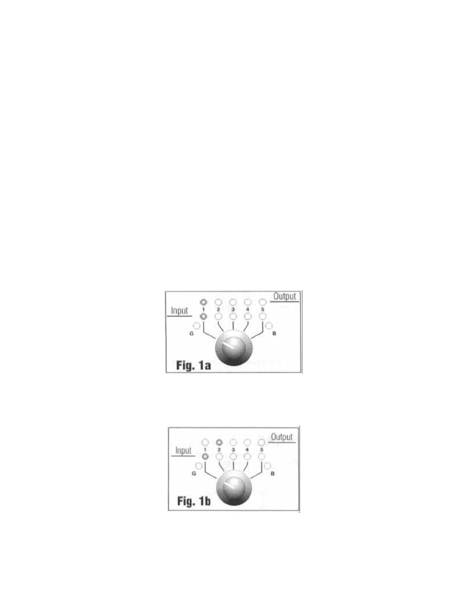
Following are some examples of possible conditions that may arise while testing
a lead (all examples show the Pin Selector Switch in position 1).
•
POSITIVE CONTINUITY
, one LED for the corresponding pin being tested
will light on the INPUT row and another LED will light on the OUTPUT row. See Fig.
La
•
CROSS WIRING
, the LEDs corresponding to the pin being tested will remain
unlit while other LEDs will light up. See Fig. lb.
•
FALSE OR LOOSE CONTACT
, the LEDs blink or flicker as you move the
cable. See Fig. 1c.