M-11s microphone input with mute-receive, M-21s microphone input with remote volume control – TOA Electronics U-13R - Unbalanced Line Input Module with High/Low Cut Filters and Mute-Receive for 900 Series (Dual RCA) User Manual
Page 9
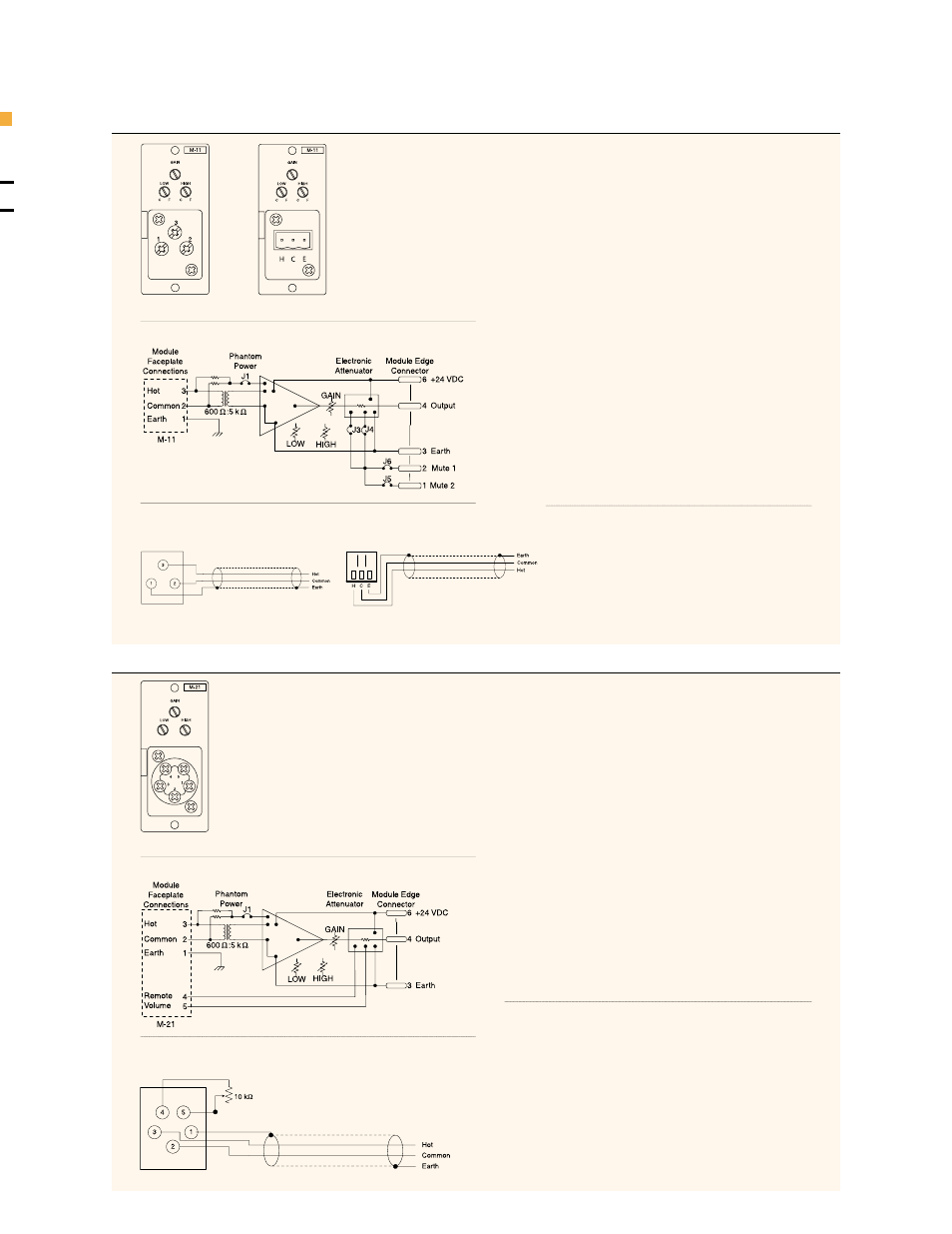
M-11
M-21
M-11S
Microphone Input with Mute-Receive
•
For Balanced, Low Impedance Microphones.
•
High and Low Cut Filters
for tone control, 4.2 kHz and
330 Hz, 6 dB/octave.
•
Phantom Power
, +22 VDC for condenser-type
microphones. Active by default, cut Jumper J1 to disable.
•
Responds To Mute Bus Activation
, via Mute SEND
module or switch-closure.
•
Responds To Both Mute Bus # 1 And Mute Bus # 2 By
Default
(cut jumper(s) to disconnect individual mute bus).
•
Two Mute Response Modes
(cut jumpers to configure):
1.
Normally-ON
- turns OFF during mute activation
(most common)
2.
Normally-OFF
- turns ON during mute activation
(functions as an ON/OFF switch, useful for zone-paging
microphones in multi-amplifier systems)
Note:
Configure the M-11 Mute Response Mode first - it
will not pass signal by default. See page 35, Jumper
Settings for details.
•
Connector:
removable terminal block (M-11S).
CONNECTOR DIAGRAM
BLOCK DIAGRAM
SPECIFICATIONS
MICROPHONE INPUT MODULES
PAGE 10
M-11S (old style)
M-11S (new style)
M-11S (old style)
Faceplate Controls
Gain, high & low cut filters
PCB Controls
Phantom power defeat, mute bus selection
Input Impedance
600 ohms, balanced transformer-isolated
Sensitivity
-70 ~ -50 dBu
Gain
32 ~ 52 dB
Noise (EIN)
-126 dBu, 200 ohms terminated
M-21S
Microphone Input with Remote Volume Control
•
For Balanced, Low Impedance Microphones.
•
High and Low Cut Filters
for tone control, 4.2 kHz and
330 Hz, 6 dB/octave.
•
Phantom Power
, +22 VDC for condenser-type
microphones. Active by default, cut Jumper J1 to disable.
•
Remote Volume Control
by connecting an external 10
k
Ω
, linear-taper potentiometer to screw terminals #4 and
#5.
Note:
Control line resistance greater than 200
Ω
will
prevent full attenuation (200
Ω
= 3821 ft. of #24 AWG
wire).
•
Tip!
You can also connect a switch between screw
terminals #4 and #5 for remote on/off operation. Closing
the switch turns the module OFF, opening the switch turns
the module ON.
•
Connector:
screw terminal (M-21S).
CONNECTOR DIAGRAM
SPECIFICATIONS
BLOCK DIAGRAM
M-21S
M-21S
Faceplate Controls
Gain, high & low cut filters, terminals for
10 kohm linear-taper pot.
PCB Controls
Phantom power defeat
Input Impedance
600 ohms, balanced transformer-isolated
Sensitivity
-70 ~ -50 dBu
Gain
32 ~ 52 dB
Noise (EIN)
-126 dBu, 200 ohms terminated
M-11S (new style)