Rear panel – Focusrite Scarlett 18i20 USB-C Audio/MIDI Interface (3rd Generation) User Manual
Page 13
13
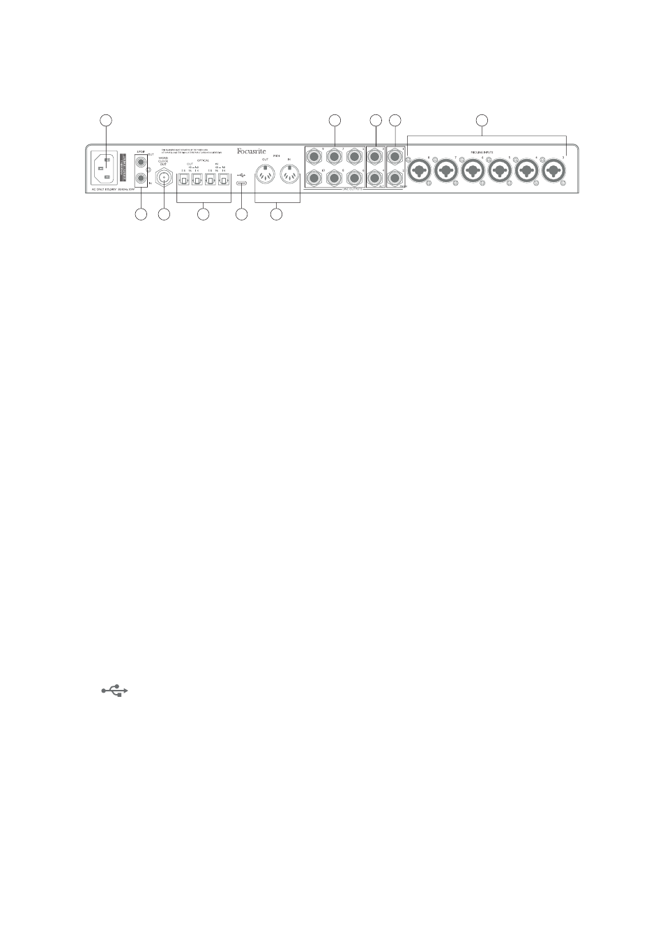
Rear Panel
24
27
25
23
26
19
20
28
21
22
19. MIC/LINE INPUTS 3 to 8 – Combo type input sockets - connect further microphones or line
level signals via XLR or ¼” (6.35 mm) jacks as appropriate. Either ¼” TRS (balanced) or TS
(unbalanced) jack plugs can be used for line level signals.
20. LINE OUTPUTS 1 and 2 (MAIN) – two balanced analogue line outputs on ¼” (6.35 mm) jack
sockets; use TRS jacks for a balanced connection or TS jacks for unbalanced. We recommend
the use of balanced connections wherever possible, to minimise grounding and hum problems.
These will generally be used for driving the main L and R speakers of your monitoring system.
However, the signals at the outputs may be defined in Focusrite Control
21. LINE OUTPUTS 3 and 4 (ALT) – connect a secondary pair of monitor speakers here in order
to use the 18i20’s ALT function. The outputs are electrically identical to Line Outputs 1 and 2.
The signals at the outputs may be defined in Focusrite Control.
22. LINE OUTPUTS 5 to 10 – six further line outputs with identical electrical characteristics to
Line Outputs 1 to 4. The signals available at these outputs are defined in Focusrite Control,
and can typically be used for driving the additional speakers in a multichannel monitoring
system, or to drive outboard FX processors.
23. OPTICAL IN and OUT – four TOSLINK connectors for handling eight channels of digital audio
in ADAT format at either 44.1/48 kHz or 88.2/96 kHz sample rates. At 44.1/48 kHz sample
rate, only the right-hand port of each pair is used; at 88.2/96 kHz sample rate, both ports are
used, with the right-hand port carrying ADAT Channels 1-4 and the left-hand port carrying
ADAT Channels 5-8. (Note that the optical input and output are disabled when sample rates
of 176.4/192 kHz are in use.) The left-hand port of each pair (IN and OUT) may alternatively be
configured to receive and transmit a two-channel S/PDIF signal from/to an external source
equipped with optical S/PDIF I/O: this option is selected from Focusrite Control. Please refer
to the Channel Listing tables in the Appendix section for more details.
24. WORD CLOCK OUT – a BNC connector carrying the Scarlett 18i20’s word clock; this may be
used to synchronise other digital audio equipment forming part of the recording system. The
source of sample clock synchronisation used by the Scarlett 18i20 is selected from Focusrite
Control.
25.
USB 2.0 port – Type C connector; connect the Scarlett 18i20 to your computer with the
cable supplied.
26. MIDI IN and MIDI OUT – standard 5-pin DIN sockets for connection of external MIDI equipment.
The Scarlett 18i20 acts as a MIDI interface, allowing MIDI data to/from your computer to be
distributed to additional MIDI devices.
27. SPDIF IN and OUT – two phono (RCA) sockets carrying two-channel digital audio signals
into or out of the Scarlett 18i20, in S/PDIF format. Note that S/PDIF inputs and outputs are
unavailable at 176.4/192 kHz sample rates. Please refer to the Channel Listing tables in the
Appendix section for more details.
28. AC mains – standard IEC receptacle.