TAMKO TAM-RAIL User Manual
Page 2
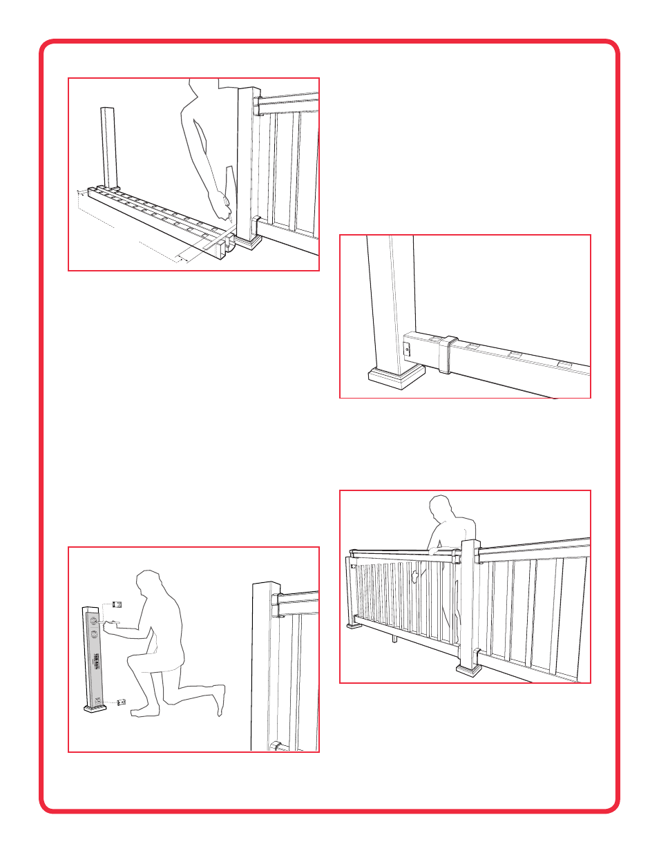
1-7/8"
MINIMUM
FIG. 3
3. Lay the bottom rail beside the posts with the pre‑routed baluster holes
facing upward and evenly spaced. Mark the rail with an additional 1/8"
removed from each end to compensate for the metal brackets. (Fig. 3)
IMPORTANT: A minimum of 1‑7/8" rail length is required from the end of
rail to first baluster on both ends of the rail. Check end spacing and shift
the position of the rail before cutting if required.
Ensure that the gap
between posts and balusters will not exceed 4".
When positioned and marked properly cut the bottom rail.
4. Lay the top rail beside the bottom rail with baluster holes aligned. Mark
and cut the top rail to match the bottom rail length and end spacing.
(Fig. 3)
5. Trim the crush block(s) to appropriate length and insert into the pre‑cut
hole(s) on the underside of the bottom rail.
NOTE: Typical crush block length is 5‑1/4" to allow for a 2" clearance
between the deck surface and bottom rail.
Be sure to check with your
local building code officials for any bottom rail clearance or rail
height requirements. Improper rail clearance or rail height could cause
a safety hazard. The formula for crush block length is: deck surface to
bottom rail clearance + 3‑1/4".
6. Use the bracket placement template to position the top and bottom
metal brackets (marked “T” and “B”) and secure brackets in place using
the six screws provided, affixing four on top and two on the bottom.
(Fig. 4) Use the 2" screws for mounting to a wood post, or the 1" screws
included in TAM‑RAIL Post Mount kit when mounting to the TAM‑RAIL
Post Mount System.
NOTE: The template is designed for a 2" clearance from deck surface to
bottom rail.
7. Slide bottom bracket covers over the bottom rail and position the rail
between the bottom rail metal brackets. (Fig. 5) Level the rail and secure
in place on both sides of the metal brackets using two of the 1" screws
provided. Snap the bracket covers over the metal brackets.
NOTE: When installing the bracket covers over the metal brackets, it may
be necessary to use a flat‑tipped screwdriver or putty knife to assist the
cover over the metal bracket.
8. Insert balusters into the pre‑routed bottom rail holes. Check with your
local code officials for any rail height requirements.
NOTE: Due to the aluminum insert in the 10' rail, the top rail of 10'
sections will rest 3/8" higher than the 6' or 8' sections. The bottom of
the top rail metal bracket will install flush with the bottom of the top rail.
This will not affect the integrity of the railing system.
9. Slide top bracket covers over both ends of the top rail. Align top rail over
the balusters and insert balusters one at a time until the top rail is fully
installed. (Fig. 6)
10. Secure top rail in place by installing two 1" screws on both sides of the
metal brackets. Snap bracket covers over the metal brackets.
NOTE: When installing the bracket covers over the metal brackets, it may
be necessary to use a flat‑tipped screwdriver or putty knife to assist the
cover over the metal bracket.
FIG. 4
FIG. 5
FIG. 6
2