Post mount instructions for concrete application – TAMKO TAM-RAIL User Manual
Page 6
Post moUnt InstrUCtIons For
ConCrEtE aPPlICatIon
ImPortant ProDUCt saFEtY anD
PrE-InstallatIon InFormatIon
The following installation instructions are provided to guide you through the installation process of
the TAM‑RAIL
®
Concrete Post Mount Kit. TAMKO
®
Building Products, Inc. shall not be held liable for
improper or unsafe installations. Failure to follow these instructions may lead to an unsafe product and
will adversely effect coverage under the Limited Warranty.
TAMKO recommends that all designs be
reviewed by a licensed architect, engineer or local building official before installation to ensure
that they are safe and in compliance with local building code requirements.
ConCrEtE anChors
TAMKO requires the use of the Hilti HIT‑RE 500‑SD adhesive anchoring system in the installation
of this post mount. The anchoring system must be installed in accordance with Hilti HIT‑RE
500‑SD Instructions and ESR‑2322. Concrete anchors must be installed in dry, normal weight
concrete with a specified compressive strength of 2,500 psi to 8,500 psi. In addition, it is the
installer's responsibility to ensure that the application and conditions for use of this post mount
are in accordance with the Requirements and Limitations provided in Appendix A of these
instructions, and TAM‑RAIL CCRR‑0118. Failure to correctly anchor the post mount in accordance
with the above requirements could result in a safety hazard.
For more information regarding HIT‑RE 500‑SD adhesive anchoring please contact Hilti at
1‑800‑879‑8000 or visit www.Hilti.com.
rEqUIrEmEnts For UsE WIth tam-raIl 6' raIlIng KIts
Post Mount
System
Minimum Concrete
Thickness
Minimum Threaded
Rod Embedment
38"
4‑3/4"
3‑1/2"
44"
5‑1/4"
4"
For TAM‑RAIL code compliance information, please see Architectural Testing, Inc. CCRR‑0118 at tamrail.com
tools rEqUIrED For InstallatIon
Tape measure, round steel brush, compressed air, torque wrench, drill, safety glasses,
hearing protection, and Hilti MD 2000 or compatible Hilti dispenser.
InstallatIon stEPs
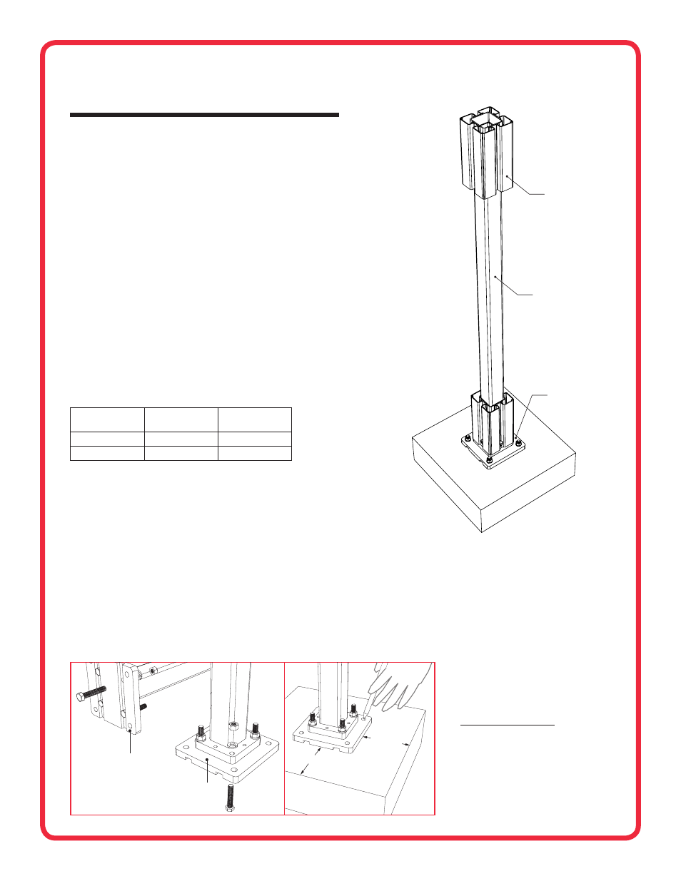
1. Assemble the concrete surface plate to the bottom of the post mount member as shown using four
of the supplied 2" coated hex bolts, 3/8" coated lock washers, and coated 3/8" hex nuts (Fig. 1).
Tighten nuts to 33 ft‑lb using a torque wrench.
Ensure that the hex bolt heads are firmly seated
inside the surface plate channels.
2. Determine the post mount location. Using the 5‑1/2" × 5‑1/2" concrete surface plate as a guide,
ensure that the distance from the edge of the concrete to the edge of the surface plate is at
least 4‑1/4". (Fig. 2)
3. Mark the location of the four concrete surface plate corner holes for drilling. (Fig. 2)
IMPORTANT: Before continuing with installation the installer must review and ensure
compliance with all Hilti HIT‑RE 500‑SD instructions and guidelines.
Post moUnt ComPonEnts:
4" × 4" Post Sleeve (1)
Pyramid Post Cap (1)
New England Post Ring (1)
Post Mount Member (1)
Guide Blocks (2)
1" Stainless Steel Screws (13)
ConCrEtE aCCEssorY KIt:
5‑1/2" × 5‑1/2" Concrete Surface Plate (1)
3/8" × 2" Coated Hex Bolts (4)
3/8" Coated Lock Washers (4)
3/8" Coated Hex Nuts (4)
5/16" × 1" Leveling Bolts (4)
3/4" Self‑drilling Guide Block screws (4)
CONCRETE ANCHORING SYSTEM
3/8" × 5‑1/8" Stainless Steel Threaded Rods (4)
3/8" Stainless Steel Washers (4)
3/8" Stainless Steel Nuts (4)
Hilti HIT‑RE 500‑SD Adhesive, 11.1 oz. (1)
(Hilti Dispenser Not Included)
SUBSTITUTION FOR THESE COMPONENTS IS
NOT ALLOWED AS SUBSTITUTING COMPONENTS
COULD CAUSE A SAFETY HAZARD.
Post mount Kit 4' x 4' x 38' for use with all tam-raIl
®
6' x 36' railing Kits
Post mount Kit 4' x 4' x 44' for use with all tam-raIl
®
6' x 42' railing Kits
FIG. 2
4-1/4" MIN.
4-1/4" MIN.
FIG. 1
BOTTOM OF CONCRETE
SURFACE PLATE
TOP OF CONCRETE
SURFACE PLATE
POST MOUNT MEMBER
CONCRETE
SURFACE PLATE
(See Fig. 4 for
more details)
GUIDE BLOCK
6
CONTINUED