4 analogue inputs, 6wiring, 7 control element – Pilz PMCtendo DD5.03/000/0/0/0/110-230VAC User Manual
Page 116
6.7
Control element
6
Wiring
Pilz GmbH & Co. KG, Felix-Wankel-Straße 2, 73760 Ostfildern, Germany
Telephone: +49 711 3409-0, Telefax: +49 711 3409-133, E-Mail: [email protected]
6-26
6.7.4
Analogue inputs
Analogue inputs
6-
][Verdr_Leiterquerschnitte_Verweis
Under “Connection cables”, please note the requirements for the:
Cable cross sections
Insulation material
][Verdr_AI_DD5
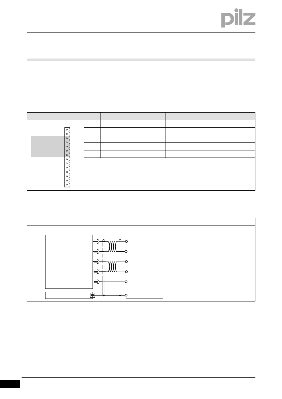
Connector pin assignment
Connector X3
Pin
Designation
Description
3
ANALOG-IN1+
Analogue input 1+
4
ANALOG-IN1-
Analogue input 1-
5
ANALOG-IN2+
Analogue input 2+
6
ANALOG-IN2-
Analogue input 2-
7
AGND
Reference earth for analogue inputs
Connection
Input circuit
Analogue input
- Signal range –10 ... +10 V
- Referenced to earth: Always con-
nect AGND (X3/7) to CNC-GND on
the control system
- Twisted pair, shielded
- Shield connection on the front plate
X3
BTB/RTO
1
BTB/RTO
2
ANALOG-IN1+ 3
ANALOG-IN1-
4
ANALOG-IN2+ 5
ANALOG-IN2-
6
AGND
7
DIGITAL-IN1
8
DIGITAL-IN2
9
DIGITAL-IN3
10
DIGITAL-IN4
11
ENABLE
12
DIGITAL-OUT1 13
DIGITAL-OUT1 14
+O1
3
ANALOG-IN1+
4
5
6
AGND
7
Servo Drive
-O1
+/- 10 V
+O2
-O2
+/- 10 V
CNC-GND
GND
X3
Shield
ANALOG-IN1-
ANALOG-IN2+
ANALOG-IN2-