Altera iopll ip core parameters - cascading tab – Altera I/O Phase-Locked Loop (Altera IOPLL) IP Core User Manual
Page 6
Related Information
Provides more information about PLL lvds_clk and loaden signals when the PLL is in LVDS mode.
Altera IOPLL IP Core Parameters - Cascading Tab
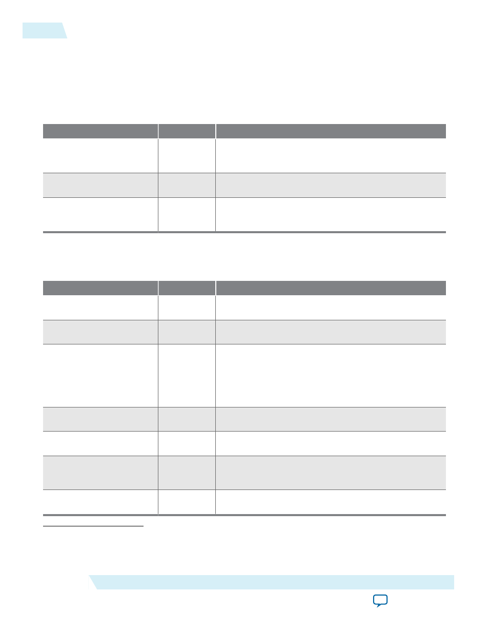
Table 3: Altera IOPLL IP Core Parameters - Cascading Tab
Parameter
Legal Value
Description
Create a ‘cascade out’ signal
to connect with a
downstream PLL
Turn on or
Turn off
Turn on to create the
cascade_out
port, which indicates
that this PLL is a source and connects with a destination
(downstream) PLL.
Specifies which outclk to be
used as cascading source
0-8
Specifies the cascading source.
Create an adjpllin or cclk
signal to connect with an
upstream PLL
Turn on or
Turn off
Turn on to create an input port, which indicates that this
PLL is a destination and connects with a source (upstream)
PLL.
Altera IOPLL IP Core Parameters - Dynamic Reconfiguration Tab
Table 4: Altera IOPLL IP Core Parameters - Dynamic Reconfiguration Tab
Parameter
Legal Value
Description
Enable dynamic reconfigu‐
ration of PLL
Turn on or
Turn off
Turn on the enable the dynamic reconfiguration of this PLL
(in conjunction with Altera PLL Reconfig IP core).
Enable access to dynamic
phase shift ports
Turn on or
Turn off
Turn on the enable the dynamic phase shift interface with
the PLL.
Generate MIF file
(3)
Turn on or
Turn off
Turn on to generate the
.mif
file for the current PLL profile.
The generated
.mif
file contains current PLL profile and a
collection of physical parameters—such as
M
,
N
,
C
,
K
,
bandwidth, and charge pump—that defines that PLL. You
can then load this
.mif
file into the Altera PLL Reconfig IP
core.
Enable Dynamic Phase
Shift for MIF Streaming
(4)
Turn on or
Turn off
Turn on to store dynamic phase shift properties for PLL
reconfiguration.
DPS Counter Selection
(5)
C0–C8, All C,
or M
Selects the counter to undergo dynamic phase shift.
Number of Dynamic Phase
Shifts
(5)
1–7
Selects the number of phase shift increments. The size of a
single phase shift increment is equal to 1/8 of the VCO
period. The default value is 1.
Dynamic Phase Shift
Direction
(5)
Positive or
Negative
Determines the dynamic phase shift direction to store into
the PLL MIF.
(3)
This parameter is only available when Enable dynamic reconfiguration of PLL is turned on.
(4)
This parameter is only available when Generate MIF file is turned on.
(5)
This parameter is only available when Enable Dynamic Phase Shift for MIF Streaming is turned on.
6
Altera IOPLL IP Core Parameters - Cascading Tab
UG-01155
2015.05.04
Altera Corporation
Altera I/O Phase-Locked Loop (Altera IOPLL) IP Core User Guide