Altera Dynamic Calibrated On-Chip Termination User Manual
Page 9
3–2
Chapter 3: Functional Description
OCT Architecture
Dynamic Calibrated On-Chip Termination (ALTOCT) Megafunction
February 2012
Altera Corporation
User Guide
After calibrated codes are shifted in serially to each I/O bank, the calibrated codes
must be converted from serial format to parallel format before the codes are used in
the I/O buffers. Use the
S2PENA
signals to complete the serial-to-parallel shifting.
Power-Up Mode Calibration and On-Demand Calibration in Quartus II
Software
Stratix III and Stratix IV have two termination related assignments:
INPUT_TERMINATION
and
OUTPUT_TERMINATION
. Termination can exist on input and
output buffers, and sometimes simultaneously.
When calibrated termination uses only the Quartus
®
Settings File (QSF) assignments,
the power-up mode of the calibration scheme is used, and on-demand calibration
updates are unavailable.
To use on-demand calibration, the ALTOCT megafunction must be instantiated into
the design. If more than one group of pins needs to be calibrated on-demand, more
than one calibration block must be instantiated.
There are two methods to associate pin groups with a calibration block:
■
Instantiate the I/O buffer primitives at the top level and connect them to the
appropriate calibration blocks.
1
All I/O banks with the same V
CCIO
can share a calibration block, even if that
particular I/O bank has its own calibration block. You can connect any
number of I/O pins that support calibrated termination to a calibration
block, unless the specific I/O pins on the device are not usable with a
particular calibration block. The Quartus II software produces warning
messages if there is no pin connected to the block.
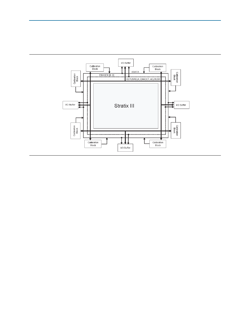
Figure 3–1. Signals for Shift-Out Codes from the OCT Calibration Block to I/O Buffers