Single channel wireless receiver – MIPRO mr515a(2ce228) User Manual
Page 3
3
4
1. Install antenna in rear (8) . Extend antenna to the fullest position. see fig.
3.
2. Connect the AC/DC adapter cable to DC 12V INPUT JACK (4), then plug
the adapter unit into an appropriate AC outlet with caution to the correct
voltage under both AC outlet and adapter marked, as shown in fig. 3.
3. Audio Output Connection:
(a) Unbalanced LevelSwitch(6) Setting Position: When connecting from
receiver's unbalanced output to the "AUX-IN" jack of a mixer or
amplifier or"Electric G uitar", switch the LevelSwitch(6) to "+10dB"
position. Low sensitivity may occur if switch to the wrong level position.
Whenconnecting from receiver'sunbalancedoutputto the "MIC-IN"
jack of a mixer or amplifier; switch theLevelSwitch(6) to "0dB"
position. Overloaddistortion may occur if switch to the wrong level
position. When using electric guitar, don't use"0dB" or "-6dB" position
as it may have generated insufficient level. There are lots of amplifiers
for Karaokemachine in today's market, h o w ever, gain of amplifier's
"MICIN" is not unified. Therefore, if distortion is encountered, please
switchthe Level Switch (6) to "-6dB" position.
(B)Unbalanced Output: Usingaudiooutputcableattached with "PHONE
PLUG" type, connect one and from the unbalanced outputjack (5) of
the receiver, a n d the other endto the "AUX-IN" input jack of the
amplifier, asshownin Fig. 3 .
(c) Guitar O utput: Using audio output cable attached with "PHONE PLUG"
type,plug one endfrom the unbalance-mixed output jack of a receiver,
and the other endto the input jack of a guitar amplifier. Switch the
LevelSwitch(6) to"+10dB" position.
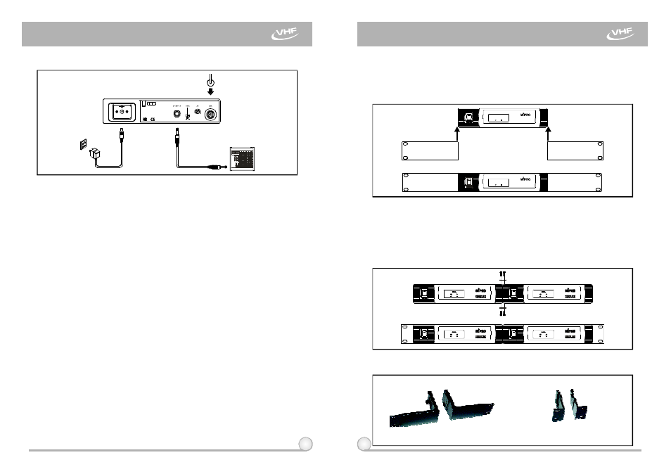
2. INSTALLATION OF THE RECEIVER
3. TWO 19/2-INCH UNITS RECEIVER INSTALLATION
Fig.3
Fig.4
Fig.5
SINGLE CHANNEL WIRELESS RECEIVER
SINGLE CHANNEL WIRELESS RECEIVER
+
-
0dB
+10dB
-6dB
WIRELESSRECEIVER
MR-515 VHF
SIGNAL
AF
RF
WIRELESSRECEIVER
MR-515 VHF
SIGNAL
AF
RF
1.
Single half-rack receiver
(a)
Push the rack mount ear optional accessory (FB-11) upwards
until it is firmly attached to the receiver. (fig. 4)
2.
Dualhalf-rack receivers
(a)
Position the connecting platesbetween the top and bottom of
the two receivers and tighten. (Fig.5)
(b)
After joining t h e 2 receivers together, push the optional
accessory rack mount ears (FB-12) upwards until they firmly
attached to the receiver. (Fig. 5)
3.
Rack-mount kit Accessories :
Rack mount kit fits 1 half-rack
FB-11
FB-12
Rack mount kit fits 2
1 half-rack
half-rack
or