Connections – ABUS Technologies Field Logger Data Acquisition/Recorder User Manual
Page 6
Advertising
ABUS TECHNOLOGIES INC.
6
Field
Logger
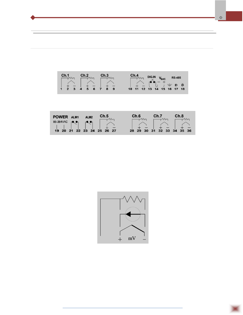
5. CONNECTIONS
Analogue Inputs
Refer to figures Upper Side Connector and Lower Side Connector, below for connections of the
input signals, power supply and alarm outputs.
Upper Side Connector
Lower Side Connector
POWER –mains input
V
BAT
– backup DC voltage (+6 to +24V
DC
). Allows continuous logging of data into memory when the AC
voltage is absent. When the Field Logger is working with the V
BAT
power only, the serial
communication and alarms are inhibited.
ALM1 and ALM2 – output alarm relays
DIG.IN – Digital input. A switch connected to this input acts as a “gate” for the logger (this function must
be configured). The DIG.IN input shares one terminal with the V
BAT
input.
Advertising