Analog inputs, Drive, 5 position connector – Applied Motion ST10-Plus User Manual
Page 17: Inside st5/10-s
Advertising
17
ST5/10-S Hardware manual
920-0027 Rev. D
2/7/14
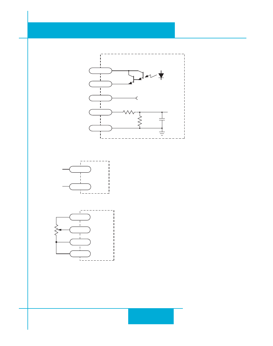
Connecting the Analog Signal to a Potentiometer or Joystick
Analog Inputs
Drive
GND
AIN
1k-10k ohm
pot
cw
ccw
+5V
AIN2
inside ST5/10-S
5 Position Connector
OUT+
OUT-
AIN
AGND
+5V
33.0K
10nF
50V
+5VDC, 10mA max
49.9K
ANA1
The ST5-S and ST10-S have one 0 to 5 volt analog input that can be used by the drive for controlling the motor
speed in velocity mode. This input can also be used to read a voltage using the SCL “IA” or “RA” commands.
0 - 5V
speed signal
signal return
GND
AIN
Connecting to an Analog Signal
WARNING - Analog input must be used with care. It is not optically isolated and may
operate improperly or could be damaged when system grounds are not compatible.
Advertising