Connecting the digital output, 5 position connector, Inside st5/10-s – Applied Motion ST10-Plus User Manual
Page 18
18
ST5/10-S Hardware manual
920-0027 Rev. D
2/7/14
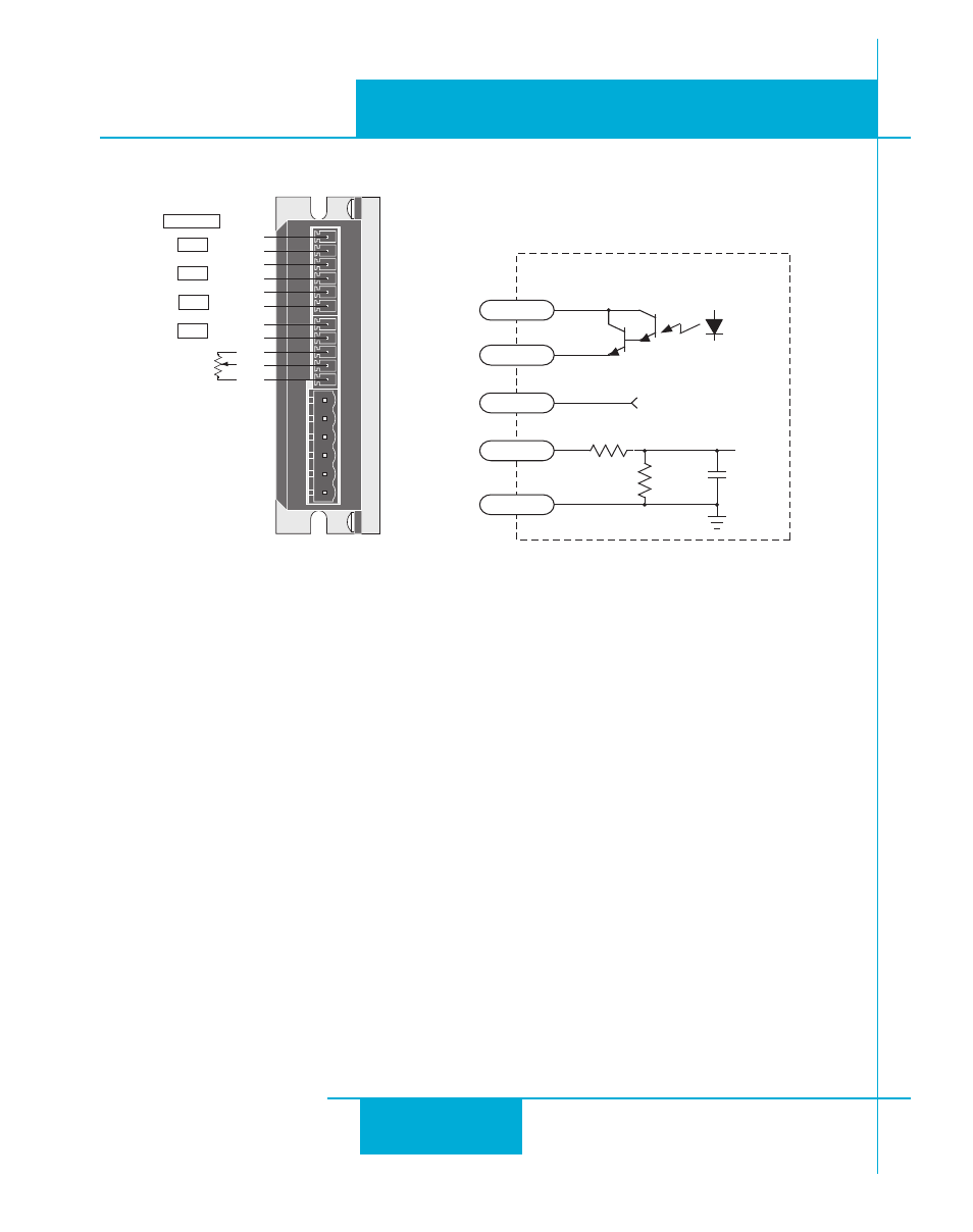
The ST5-S and ST10-S drives include one digital output that can be used in one of five ways:
Brake: output can be configured to control an electric brake relay, automatically releasing and engaging as the
drive requires.
Motion: indicates when the motor is moving.
Fault: closes when a drive fault or alarm condition occurs. The red and green LEDs will flash an error code.
Tach: produces pulses proportional to the distance traveled (and thereby a frequency that is proportional to mo-
tor speed.)
General purpose digital output, controlled by the SCL SO, FO, IL and IH commands.
The output features separate + and - terminals and can be used to sink or source current.
Diagrams of each type of connection follow.
Do not connect the output to more than 30VDC.
The current through the output terminals must not exceed 10 mA.
Connecting the Digital Output
GND
AIN
+5V
OUT-
OUT+
EN-
EN+
DIR-
DIR+
STEP-
STEP+
HUB & SCL
IN 1
IN 2
IN 3
OUT 1
inside ST5/10-S
5 Position Connector
OUT+
OUT-
AIN
AGND
+5V
33.0K
10nF
50V
+5VDC, 10mA max
49.9K
ANA1