Casella CEL CEL-181 User Manual
Page 5
Casella USA
17 Old Nashua Road #15
Amherst, NH 03031-2839
2 Technical
Description
The CEL-180 meets all the essential require-
ments for Precision Sound Level Meters. These
are defined in the International Standard IEC
651 type 1 (IEC 179) and the British Standard
BS 4197. As this instrument conforms to the
highest standard of accuracy it is no longer
necessary to make any special provision for
possible instrumentation errors when applying it
to industrial situations. The CEL-181 meets the
lower accuracy requirements outlined in the
relevant sections of IEC 651 type 2, BS 3489
and ANSI S1.4
The microphones employed in the CEL-180
Noise Dose Meters are half-inch (12.7mm)
Precision Measurement Microphones type
CEL-186. These microphones have extremely
uniform frequency response and very high
calibration stability. The signal from the
microphone is passed to the main unit over
approximately 0.5m of cable where they are
amplified and applied to an 'A' frequency
network. The CEL-181 types have similar
configuration but employ a 12mm piezo-electric
type of microphone.
A wide dynamic range RMS detector is used in
the device and this feeds a separate amplitude
weighting circuit. The device has, therefore, a
very wide degree of flexibility in its specification
allowing the dynamic range; count rate, q factor
and RMS time constant to be specified within
wide limits. Basically, the RMS detector has a
range of 40dB plus a 23dB crest factor giving a
total input range of 63dB, whist the voltage to
frequency converter can handle a ratio of
10,000:1 (213). The converter can, therefore,
handle the full 40dB RMS level in the q3 mode
as this signal will obviously double in
significance 13 times (40/3). In the q4, q5 or q6
modes the significance of the signal becomes
much less severe with increasing amplitude;
when q = 6, for example, we only have 6.6
doublings so it is only in the q3 case that we
have to consider the voltage to frequency
converter as a possible limitation. The RMS
detector will, however, control all modes of the
instrument and, as mentioned before, this will
handle levels over the range of 40dB with an
additional 23 dB for impulses. To protect against
incorrect answers being given, the instruments
employ a dual overload indication system. The
overload indicator will be set by either an
instantaneous level 63dB up on the threshold or
by an RMS level that is 40dB up. These
overload indication levels can be reduced to
lower levels if required, e.g. to conform to the
USA OSHA regulation the RMS overload level
should be set at 115dB(A) slow.
The active circuit elements are mounted on
glass fiber double-sided printed circuit panels
and extensive use is made of integrated circuits.
The assembly is contained within a high impact
ABS case that has neoprene surface treatment.
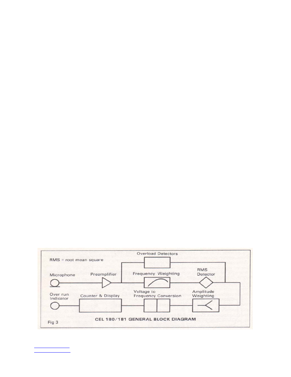
A general block diagram of the instrument is
shown in Fig 3. The various versions have
similar layout of the main circuit elements and
differ only in detail. This diagram is provided for
general information only - for full technical and
servicing information reference should be made
to the service manual.
Figure 3
www.casellausa.com
Page 5 of 14
tel:
(
800) 366-2966
27 Jan 2006
fax: (603) 672-8053