Casella CEL CEL-181 User Manual
Page 7
Casella USA
17 Old Nashua Road #15
Amherst, NH 03031-2839
www.casellausa.com
Page 7 of 14
tel:
(
800) 366-2966
27 Jan 2006
fax: (603) 672-8053
3.2.2 Controls and Indicators
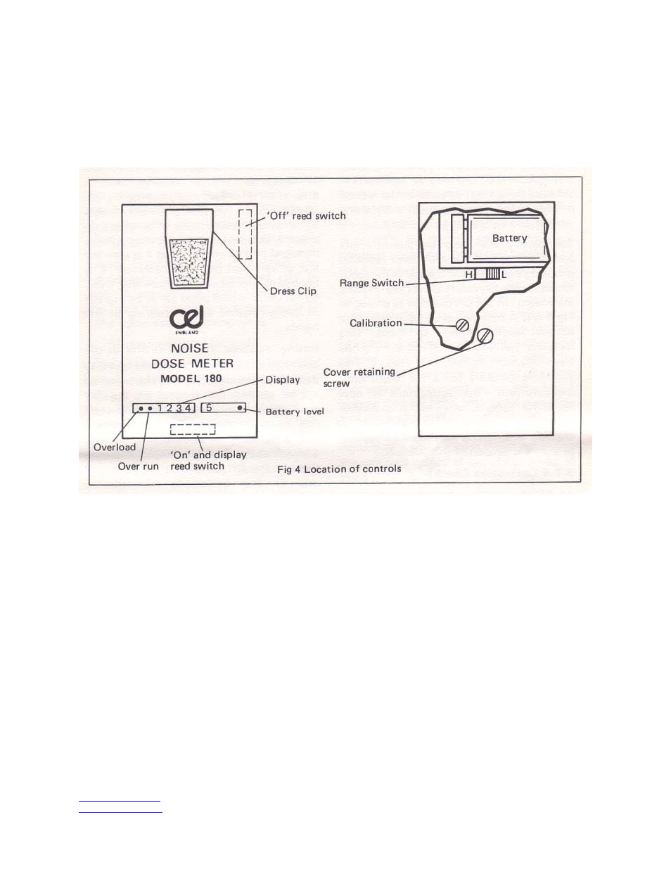
The diagram in Fig 4 gives the location of the
various controls and indicators, the functions of
which are as noted below:
Figure 4
ON/DISPLAY
This control is a magnetically operated reed
switch inside the instrument, It is activated by
placing the bar magnet on the case in the area
indicated in Fig 4. The action of placing the
magnet in this position will cause the instrument
to latch on. The battery level indicator will flash
continuously to indicate that the instrument is
operating, Whilst the magnet is left in this
ON/DISPLAY position the display will be
illuminated enabling the content of the counter to
interrogated. When the magnet is remove the
display will be extinguished but the instrument
will continue operate.
OFF/RESET
A second magnetic reed switch is located in the
top of the instrument and this will, when
activated by the magnet, switch the Noise Dose
Meter off and reset the counter to zero.
ON/BATT LEVEL
This LED indicator will flash whenever the
instrument is operating as long as there is
sufficient battery power for a further eight hours
operation. If the switch-on procedure is followed
and the ON/BATTERY LEVEL indicator fails to
flash when the display is extinguished the
battery will not last for a full eight-hour
measurement.
OVERLOAD
This indicator will latch on if an instantaneous
level in excess of the instrument's dynamic
range is logged during the measurement
sequence. It will be reset whenever the counter
is zeroed.