Secondary dns - ( dhcp no ), Other setups - ( dhcp no ), Manual date and time setup – CIRCUTOR EDS Series User Manual
Page 2: Ping system, Network parameters setup (software), Web server, Xml server, Digital inputs, Digital outputs, Rs-485 expansion bus
EDS
M98237501-03-13A
2.2.8.5.- Secondary DNS -
( DHCP no )*
To configure the secondary DNS server, carry out the same
procedure as with the Primary DNS.
2.2.8.6.- Other setups -
( DHCP no )*
After configuring the secondary DNS, the other setup screens
correspond to the same ones as in the activated DHCP mode;
consequently the setup procedure will be the same as the one
for sections:
-
-
-
-
2.2.5.- AMB® - Active Mode Bridge
-
-
2.2.7.- Confirm Changes - ( DHCP YES )
2.2.8.7.- Manual Date and Time setup
If there is no authentication configuration by the DHCP
system, and if there is no Primary and Secondary NTP server
available, EDS allows the time and date to be configured
manually when validating the changes by displaying the
caption
adjust clock. The date and time are displayed on
screen with the following format:
YYYY-MM-DD HH:MM. To
configure them, press the
Scroll RIGHT key, activating the
edition cursor in the first digit. Use the
Scroll up and Scroll
down buttons to establish the parameters of the numerical data
entry. After establishing the parameters, press the
Scroll RIGHT
key twice until the edition key disappears, and then validate
the data with the
Scroll down key, leaving setup and validating
the configuration.
When the setup is validated, the
DONE caption appears,
returning to the main screen.
2.2.9.- Display of setup parameters
To display the setup parameters, the user must enter the
setup menu by simultaneously pressing the
SCROLL RIGHT ,
SCROLL UP and Scroll down keys. The user must Press the Scroll
down key twice for complete visualisation of the device
configuration.
If a user and password are available even when the user does
not have one, all the setup parameters can be visualised
without being able to change them (asterisk in top left hand
corner).
2.2.9.1.- Ping system
To confirm IP connectivity via a Local Area Network (LAN) or
the Internet using a DSL or 3G router, the user sometimes has
to know if the EDS device has this IP access or if the unit has
particular access to a certain host.
To do this, EDS has a
PING section, from which the user can
carry out an IP connectivity test with an IP address or name,
emulating the ping command of a conventional operating
system.
The device displays the physical address within the setup
menu, as shown in section 2.2.1.- MAC address. Press the
SCROLL RIGHT key to go to the on-screen caption HOST PING. To
enter the name or IP address to carry out the ping test, press
the
Scroll RIGHT key to activate the edit cursor in the first digit.
Press this key and the
Scroll up and down buttons to establish
the parameters of an alphanumeric data entry of up to 20
digits. After the data is entered, press the
Scroll RIGHT key
twice until the edit key disappears, and then validate the data
with the
Scroll down key, by going to the next screen.
When the data is validated, the screen displays the
DOING PING
caption and will then show the results:
-
PING RESULT: OK - a response was obtained from the host
-
PING RESULT: time out - no response was obtained from
the host
When a result is obtained by the device, press the
Scroll down
key and the device goes back to the by default display
screens.
2.2.10.- Internal setup web site
After establishing the parameters with the keyboard and
connecting to the Ethernet, the device has a setup web site
where the user can integrally modify the data entered with the
keyboard. The setup web site is at the http address below:
-
-
Where xxx.xxx.xxx.xxx is the IP address assigned by the user.
Where name_dhcp is the name assigned and authenticated
by the name server of the local area network (LAN).
2.3.- Network parameters setup (Software)
Configuration of addressing can be done in the same way as
using the keyboard via the IPSetup.exe file, available on a
CD supplied with the device.
2.3.1.- Fixed IP assignment
To assign a fixed IP address, enter the MAC address
displayed on the device screen as shown in section 2.2.1.-
MAC address address, the format of which is
00:26:45:XX:XX:XX.
In the Address field, enter the IP address being configured;
do the same with the (Netmask) and the (Gateway) port if
necessary. After entering the device setup, press “Setup” to
send the setup to the equipment.
2.3.2.- DHCP IP assignment
To assign the DHCP name, activate the option using the
upper right hand arrow and select On. Once the setup fields
have been enabled, enter the MAC address.
In the Address field, enter an unused, temporary IP address,
which is within the working range of your computer. In the
Host Name field, enter the DHCP name to be assigned to the
equipment. Optionally, the user can configure the parameters
of the ClientID field. The default VendorID of the device is
CIRCUTOR.
2.3.3.- Setup web site
Once connection to the Local Area Network (LAN) is
established and the IP address or DHCP name is configured,
the device has an internal web site where the user can
integrally modify all the parameters concerning network
configuration (2.2.10.- Internal setup web site), and even the
time and date data.
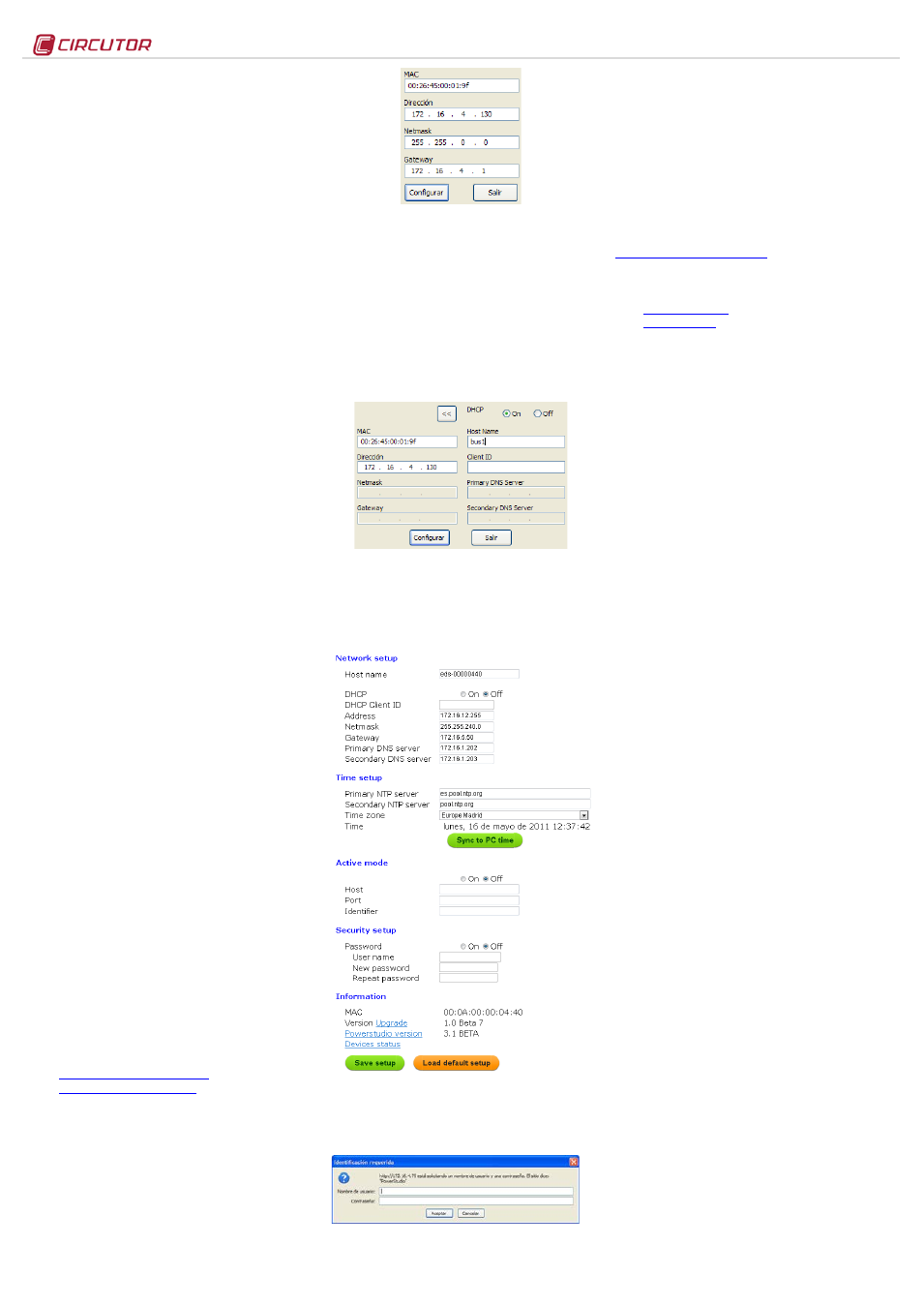
2.3.4.- Access via password
If an access user name and password have been
parameterised, the device requests these access parameters
when trying to access via the web site in the following pop up
screen:
3.-
Operation
EDS is an energy efficiency manager with a Web server
display, from which the user can see the status of the device
inputs and outputs in real time, as well as any possible action
to be taken.
As well as serving the data stored internally via the Web, the
device has an XML server, enabling the user to send GET and
PUT type requests.
3.1.- Web Server
Once the Ethernet addressing is configured and integrated
into the Ethernet network, the device variables are visible to
the user via a conventional Internet Explorer browser (with
Java plug-in installed on the computer
Another access interface
is the PowerStudio Scada Client.
To see the Web display interface, the user must access it via
the http address below:
-
-
Where xxx.xxx.xxx.xxx is the IP address assigned by the user.
Where name_dhcp is the name assigned and authenticated
by the name server of the local area network (LAN).
3.2.- XML server
The XML server is an excellent integration tool for external
applications. EDS has a server available whose access
requests are identified in this manual (see XXX).
3.3.- Digital inputs
The device has a total of 8 digital inputs, whose function is to
count energy impulses coming from external sensors, or for
detection of the logical status of the input. The contacts
associated to the digital inputs of the device must be voltage-
free dry contacts.
3.3.1.- Impulse meter function
The electronic meters have an impulse output that is
proportional to the recorded power. With its inputs, EDS is a
centralising unit with 8 digital inputs (opto-coupled) for reading
impulses from electricity, water, gas, etc. meters. The value of
these impulses is associated to 8 memory records, stored in a
non-volatile memory.
Each registry is 32 bits (4 bytes), so it counts a maximum of
up to 4,294,967,295 impulses. When a memory record
reaches this value, the meter is reset back to zero.
The minimum duration of the impulse or status change of the
digital input must be 50 ms. The minimum time between two
successive impulses must also have a minimum duration of
50 ms. This represents a maximum sampling frequency of 10
Hz.
Its Web server and internal memory enable the user to extract
graphics and tables of impulses received during a certain
period (table and graphic function).
3.3.2.- Input logical status function (0/1)
The 8 digital inputs in the device are voltage-free and have an
input logical status detection function. This means that when a
bridge is set up between the common and one of the digital
inputs, the device detects that the input has closed, and
displays the status via both communications servers.
3.4.- Digital outputs
The device has 6 relay digital outputs. The user can use
remote control to carry out actions on the outputs (open,
close, create an impulse).
These actions can be manual, or via programming in the
events section of the device (see PowerStudio Scada
manual).
3.5.- RS-485 expansion bus
The device has an RS-485 communications bus that allows it
to communicate with external peripherals, act as a
communications master and store data recorded in its 200Mb
cyclic memory.
Its Web accessibility and memory enable the user to view
data coming from devices connected to the bus in real time,
and easily and simply view graphics and tables of the
parameters registered by the device.
As well as linking communications with devices connected to
its RS-485 communications bus, the device also has the
capacity to make connections via IP connectivity (local or
remote), either through an IP via addressing or DHCP name.
To add devices to the EDS energy device setup, the user
must install the PowerStudio or PowerStudio Scada
application, so as to export a new setup of the device, adding
new analyzers or slaves connected to the unit.
EDS allows configuration of up to 5 slave devices connected
to its network.
3.6.- Additional PS/PSS features
To configure the other system features, read the PowerStudio
/ Scada Editor manual. It has all the information the user
needs about: