CIRCUTOR EMF-EMB Series User Manual
Page 8
----- Static switching modules EM ---------- M98116701-20 Pág: 7
5.2 Zero Switching Control Board (CPC).
The CPC control board receives the enable signal for ON-OFF operation of the static switch.
This enable signal is usually given by a PF regulator (usually a COMPUTER...f) and is
connected to terminals A and C. The static switch operation according to this signal, is resumed
in table 5 in the technical characteristics.
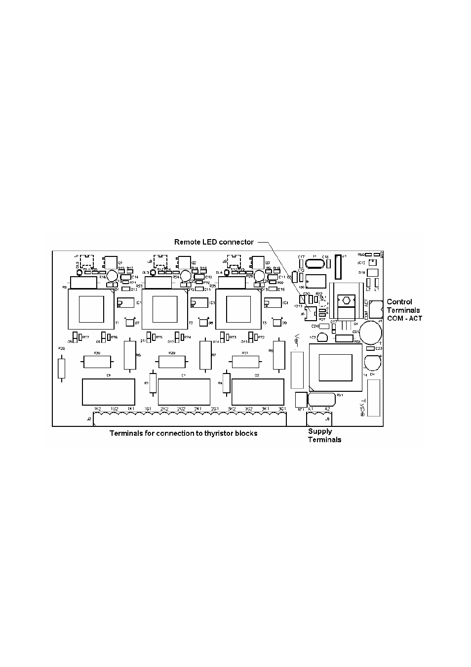
The CPC has three red LEDs , one for each phase , showing whether the phase is ON or OFF.
The card has also a set of 12 terminals connected to the thyristors through optocouplers, to obtain
the synchronism for switching at zero voltage. The CPC must be supplied from an auxiliary
source from terminals B1 and B2 (See module label for nominal value). The ENABLE
terminals, ACT-COM, are connected to external terminals A and C.
Notice that all the synchronism between the CPC card and the thyristor blocks are coupled
through optoisolated devices and the firing signals are coupled through pulse transformers,
therefore , the electronic circuits and the power block are galvanically isolated.
Figure 4 .- Layout of CPC printed circuit board
6
START UP OF PF COMPENSATORS BASED ON EM MODULES.
To start up static PF compensation equipment, based on the EM modules, follow the steps
below.
6.1 Initial checking (before connecting to supply)
• Check that the rated voltage for the EM modules, shown in the characteristics label, conforms
with the rated voltage available in the site where the equipment has to be installed
• Check that the EM modules are supplied through the auxiliary supply terminals B1-B2 with
the rated voltage value shown in the label.
• Check that the power of EM modules is in accordance with the size of the capacitors which
have to operate.