CIRCUTOR EMF-EMB Series User Manual
Page 9
----- Static switching modules EM ---------- M98116701-20 Pág: 8
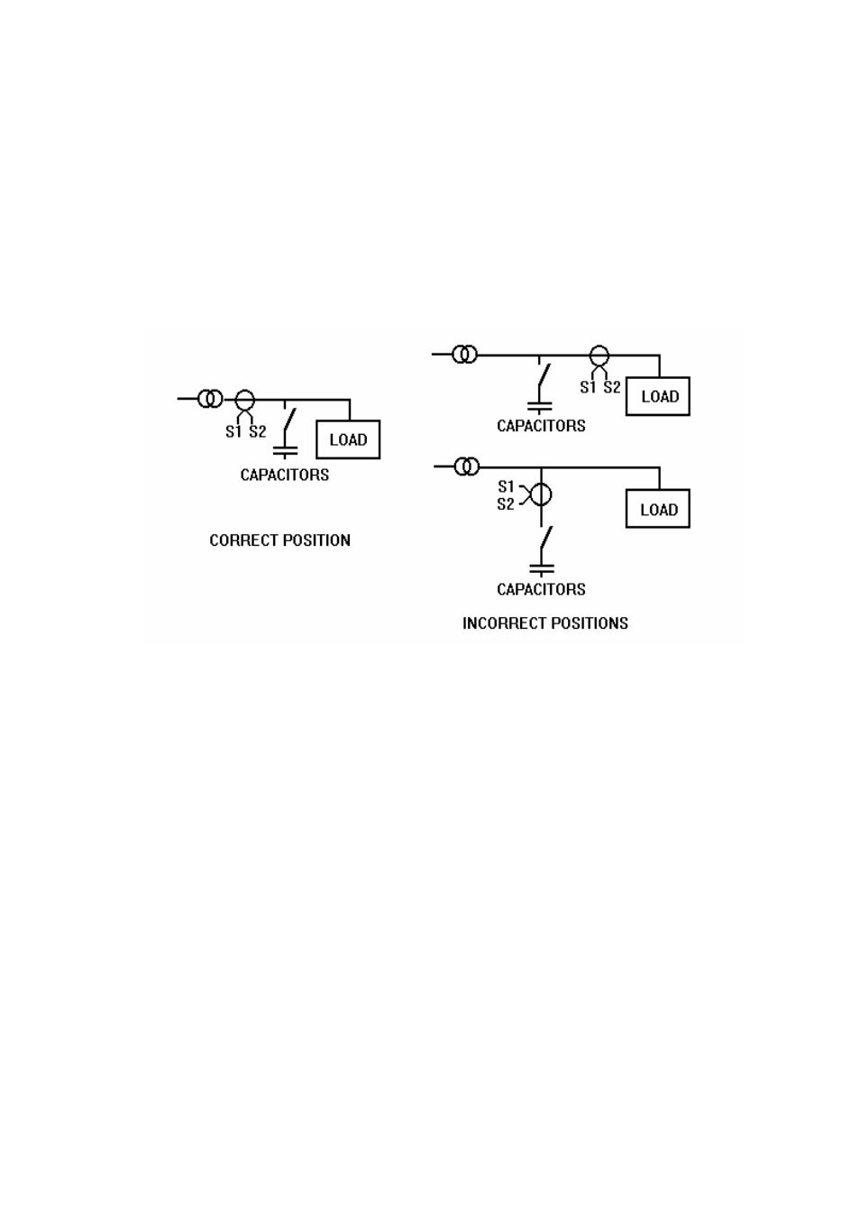
• Check that the connections between the EM modules and the capacitors correspond to one of
the figures 2 o 3.
• The external connections of a static capacitor bank are identical to those of a standard
capacitor bank using electromechanical switchgears. The section 10 shows a diagram
illustrating the internal and external wiring of a single EM module, including the connections
between the CPC board and the thyristor blocks.
• Check the connections between the EM modules , the PF regulator (COMPUTER...f) and
the current transformer (CT). For details concerning the regulator adjustment see the
instructions manual of COMPUTER...f. See also the figure 5 showing the right location of
CT in the installation.
Figure 5.- Location of the current transformer (CT)
6.2 Checking immediately after the supply connection
¡ ATTENTION! Before any attempt of manipulation on the PF correction equipment wait 5
minutes for capacitors discharge after the supply has been removed.
In static capacitor banks, where the load has great fluctuations, it must be considered normal that
the switches operate very often. Nevertheless if the PF regulator operates the capacitor steps very
quickly when the load remains constant, check the COMPUTER...f adjustments.
7
TROUBLE SHOOTING
The capacitor bank should operate only if there is a minimum load. If the equipment does not
work properly check the following points:
• If the display of the COMPUTER...f does not light or gives a very slight bright , check the
supply voltage and the fuses (power and control fuses)
• If the display of the COMPUTER...f shows an error, see the COMPUTER... instructions
manual. Check also the CT connections
• If the LED pointing to the letter C is lighting , means that the COMPUTER...f sees a
capacitive load. If an inductive load is expected, then check the CT phase settings and the CT
connections.