2 isolation and external protection items, 3 auxiliary control voltage, Isolation and external protection items – CIRCUTOR OPTIM Series User Manual
Page 11: Auxiliary control voltage, N 5.3.3), N 5.3.3
OPTIM SERIES
11
5.3.2
Isolation and external protection items
-
In the case that the capacitor bank does not have an internal switch or isolation switch, the
capacitor bank must be connected to a line that has a switch or external isolation switch.
The protection elements, isolation switches and/or switches that are added
externally to the capacitor bank must be of a minimum size to withstand a
current 1.5 times greater than what is indicated on the label (REBT, ITC-BT-
48)
In the case that an earth leakage detector for the capacitor bank is installed, its
sensitivity and trip delay must be adjustable.
-
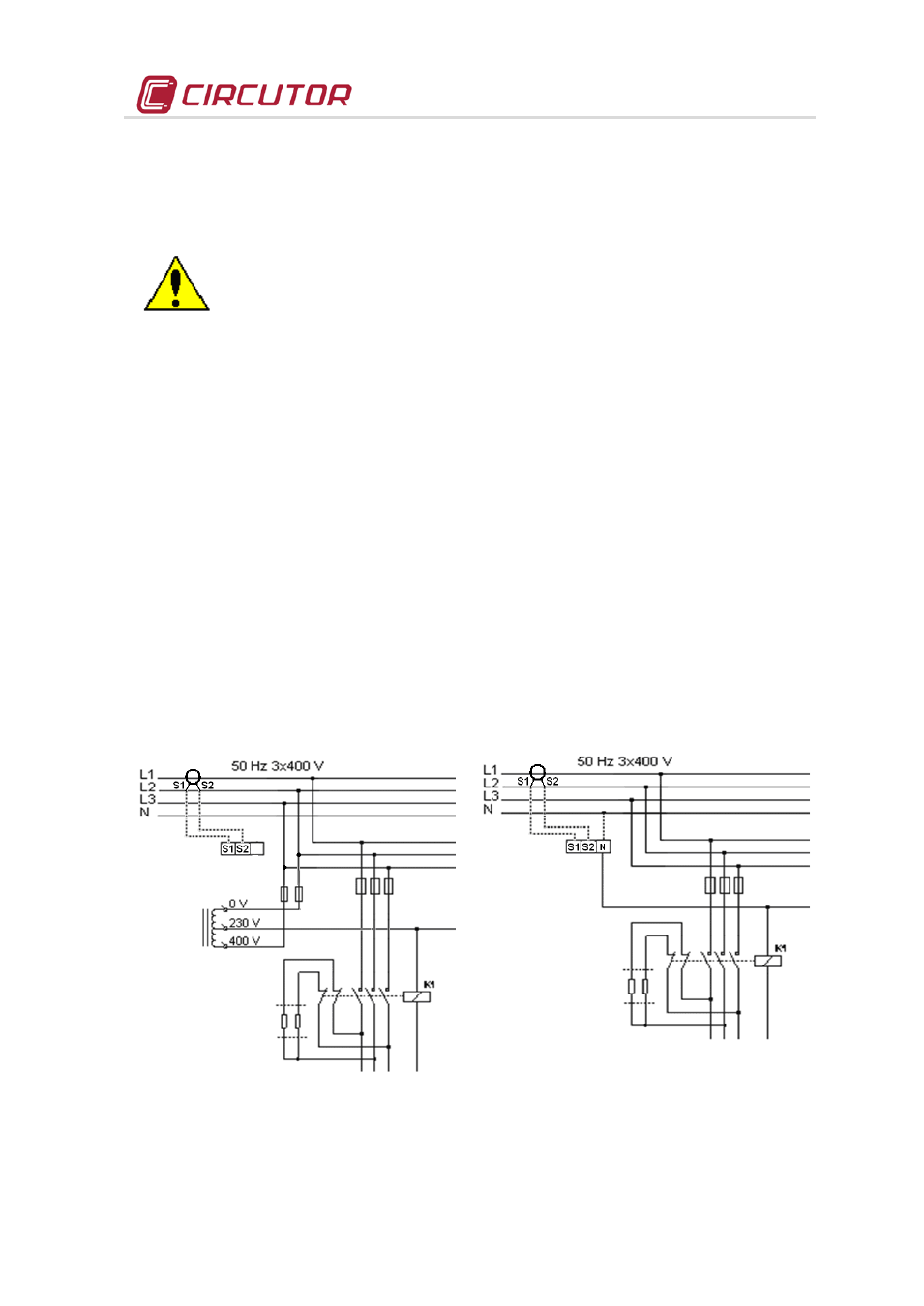
When the bank is connected to the grid, it is recommended that the current transformer
(CT) is placed on the phase going to L1 (black cable).outputs S1 and S2 of the CT must
be connected to the terminals with the same name
5.3.3
Auxiliary control voltage.
Control circuits are defined as those related with regulator output relays and the capacitor's
operating contactors. These circuits are usually fed to a 230 Vac auxiliary circuit(most common
case) or other voltages such as 110 Vac (common in the case of capacitor banks at 500 v or 690
V). There are two possible ways of feeding the circuit
•
Bank with auxiliary voltage obtained from an internal AUTOTRANSFORMER
Does not require connection of the external neutral. The label indicates U
aux
/f … internal
•
Bank with auxiliary voltage obtained between PHASE-NEUTRAL
Requires connecting the external neutral to terminal N (see
Fig. 5-2 and Fig. 5-4 The label indicates U
aux
/f … (control voltage)
Fig. 5-1 .- Auxiliary power supply with
autotransformer
Fig. 5-2 .- Auxiliary power supply with neutral