CIRCUTOR OPTIM Series User Manual
Page 14
OPTIM SERIES
14
• Ensure the inner circuit breaker that starts the regulator (shown as the operating protection in
fig. 4.3) is connected
• Apply power to the panel and check that the regulator display illuminates immediately.
Otherwise, stop and check the previous step.
• Check the regulator's cos ϕ indication. If the indication is out of range 0.5 to 1, it may be
possible that the current transformer and / or the power supply to the regulator are improperly
connected. Most of the regulators use only one current transformer. In this case, connect as
per fig. 6-2 (place the current transformer on phase L1 and take the power voltage from
phases L2 and L3)
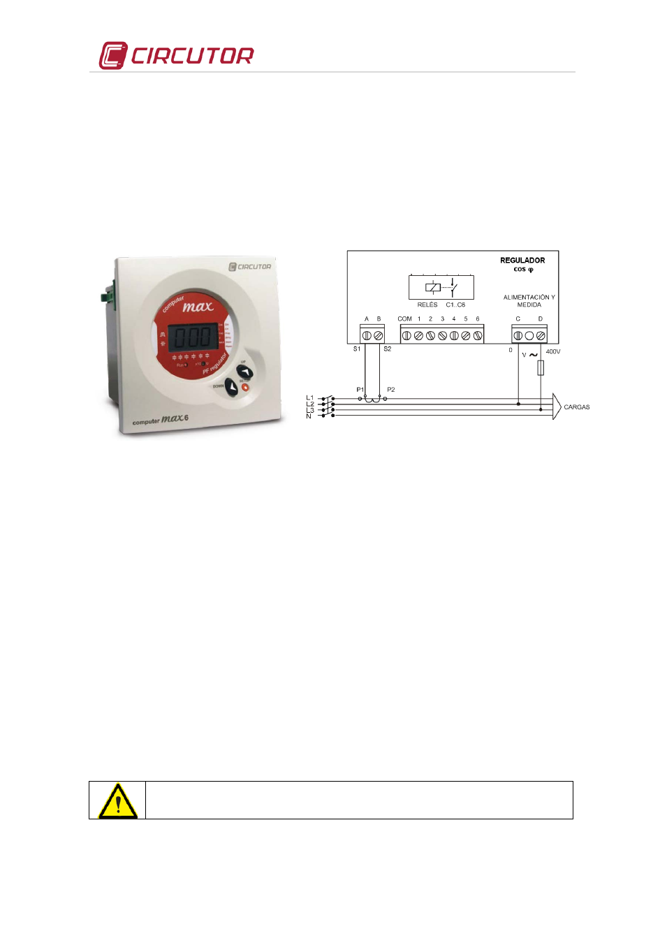
Fig. 6- 1.-
computer Max regulator
(picture provided as an example. It may not
coincide with the model used on your unit).
Fig. 6-2 .-
Type connection of a regulator with only one CT
(If using computer Plus, 3 current transformers are used. Refer to the
computer Plus specific manual)
• Once ensured that the regulator is properly connected, adjust the regulator parameters for the
installation you are attempting to compensate. To accomplish this, follow the regulator's
instructions manual included with the battery.
6.3
Checks once the bank is connected and the regulator has been adjusted
• After start-up, make sure that the equipment is operating correctly. A sign of proper operation
is a cos
ϕ next to a 1 indicated on the display. In addition, the reactive meter must stop.
• Check that the power supply voltage does not go above the nominal value +10% (IEC 60831-
1)
• Check the current absorbed by each capacitor. Under normal conditions, it must be close to
the nominal value indicated on its characteristics plate and never exceed 1.3 times this value
constantly.A continuous consumption over the nominal value may be caused by the presence
of harmonics in the grid or an excessively high power supply voltage. Both circumstances are
harmful for capacitors.
• In accordance with the IEC 60831-1 Standard, the capacitor is prepared to operate
continuously at up to 10% overvoltage for up to 8 hours, every 24 hours.
Check the working temperature of the capacitors after they have been operating
for 24 hours. The capsule must be below 40 ºC