Absorption filter ------ user manual – CIRCUTOR FAR-Q Series User Manual
Page 5
------ Absorption filter ------ User Manual,
M98206701-03-07A ------ Page 4 of 11------
3) Harmonic current capable of absorbing.
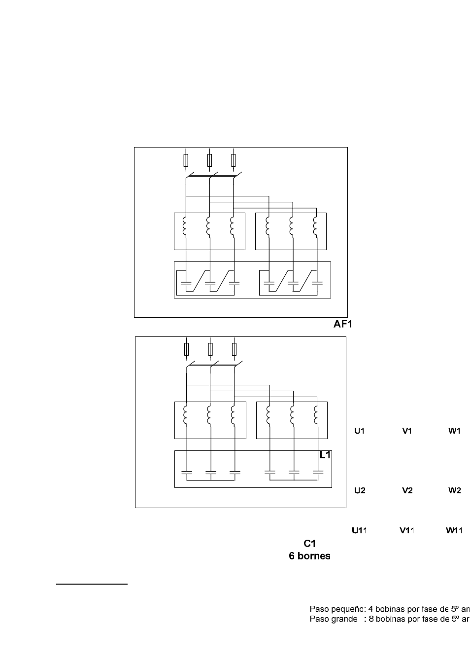
Each step is formed by 2 reactors and a 6 terminal capacitor which contains 2 three-
phase, 3 terminal capacitors each electrically insulated. The operating principle of this
design is that each reactor is connected to each of the three capacitor terminals forming
an LC set tuned to a frequency close to the 5th harmonic and another set tuned near to
the 7th harmonic. The following diagram shows how the step is formed:
Fig. 1 – Standard type at 400V 50Hz, triangle connection
L1
L2
C1
6 bornes
U11
V11
W11
U12
V12
W12
U1
V1
W1
U1
V1
W1
U2
V2
W2
U2
V2
W2
AF1
Paso pequeño: 4 bobinas por fase de 5º armónico 2 bobinas por fase de 7º armónico
Paso grande : 8 bobinas por fase de 5º armónico 4 bobinas por fase de 7º armónico
Fig. 2 – Standard type at 480V 60Hz, star connection
Filter regulation
Filter regulation is via a conventional power factor regulator as with any other standard
capacitor bank. (See regulator manual)