Description – CUE inputCUE-W User Manual
Page 5
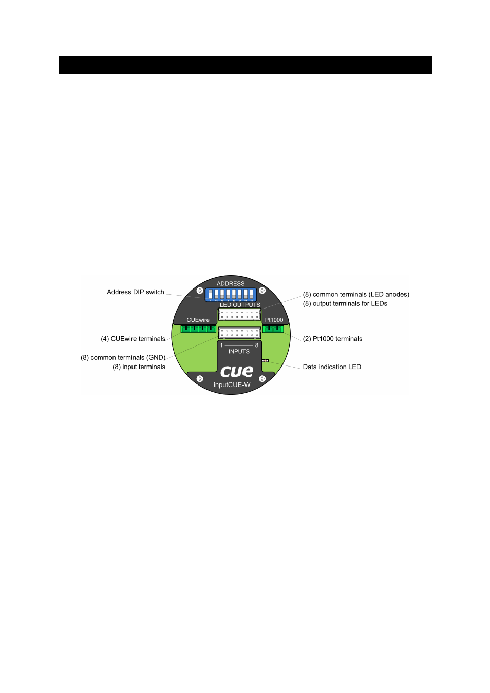
2. Description
The enclosure of inputCUE-W allows simple installation into standard European electrical wall box.
Inputs and outputs are connected via 16-pin connector JST, type PHDR-16VS.
Every input has 2 terminals (pins on input connector), one terminal is input signal, second terminal is
input common (GND).
Outputs are connected via the same type of 16-pin connector. Every output has 2 terminals, one
terminal is output signal (LED's cathode), second terminal is output common (LED anodes).
Two sets of 16-pin connector with 400 mm cables are delivered with this unit. Every input and output
has its unique colour of cable (see colour table below).
Temperature sensor Pt1000 (not delivered with this unit) is connected via 2-pin terminal (Phoenix
3,5 mm).
Standard CUEwire is connected via 4-pin terminal (Phoenix 3,5 mm) and it includes power supply
24 VDC and RS-485 data.
The address DIP switch sets ADDRESS of the inputCUE in the range 0 to 207.
Data indication LED indicates data activity on the CUEwire. This activity is indicated also if any of the
inputs is switched. This feature allows to test all inputs without connection to a control unit, just with
power supply connected.
User Manual inputCUE-W
www.cuesystem.com
Page 5 of 14