Monroe Electronics 948A User Manual
Page 16
Advertising
15
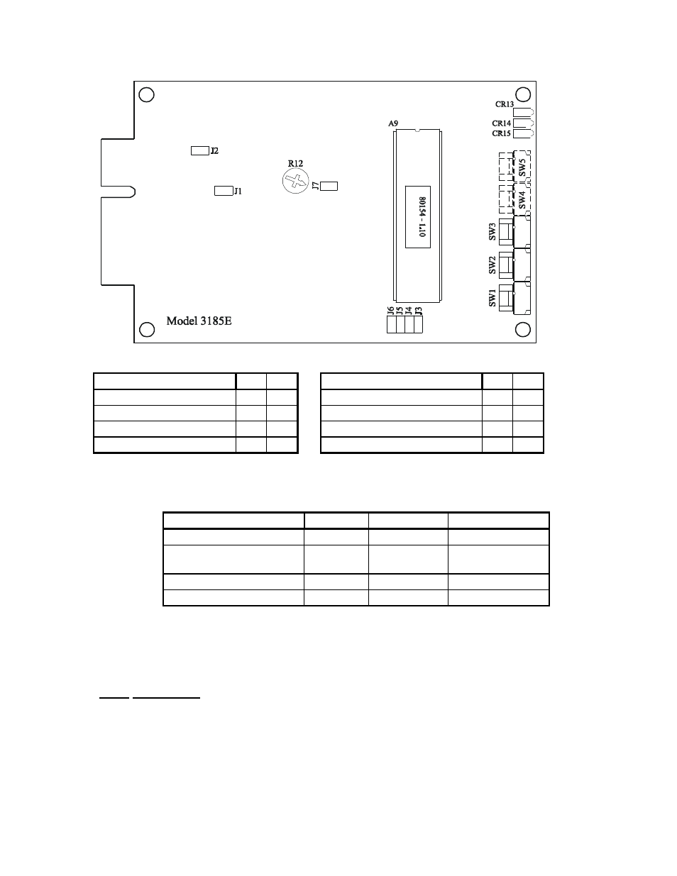
NUMBER OF DIGITS
J6
J5
RELAY OUTPUT MODE
J3
J4
1
X
X
LATCHING
O
O
2
X
O
MOMENTARY
X
O
3
O
X
ALTERNATE
O
X
4
O
O
20 MINUTE LATCH
X
X
X = JUMPER INSTALLED
O = JUMPER REMOVED
R12 = INPUT SIGNAL LEVEL RANGE ADJUSTMENT
JUMPER
OPEN
SHORTED
INPUT IMPEDANCE
J2
10k
Ω
n
600
Ω
INPUT TERMINATION
J1
BALANCED
UNBALANCED
n
5 MINUTE RESTORAL
J7
ENABLED
n
DISABLED
20 MINUTE RESET
J3, J4
DISABLED
n
ENABLED
n
= FACTORY SETTING
FIGURE 3
Jumper Locations
Input Impedance:
Input impedance may be either 10 k
Ω
or 600
Ω
. The J2 jumper determines the input
impedance of the 3185E. Install a jumper at position J2 to terminate the audio input in 600
Ω
.
Consult FIGURE 3 for the J2 jumper location.
Advertising
This manual is related to the following products: