Monroe Electronics 948A User Manual
Page 18
17
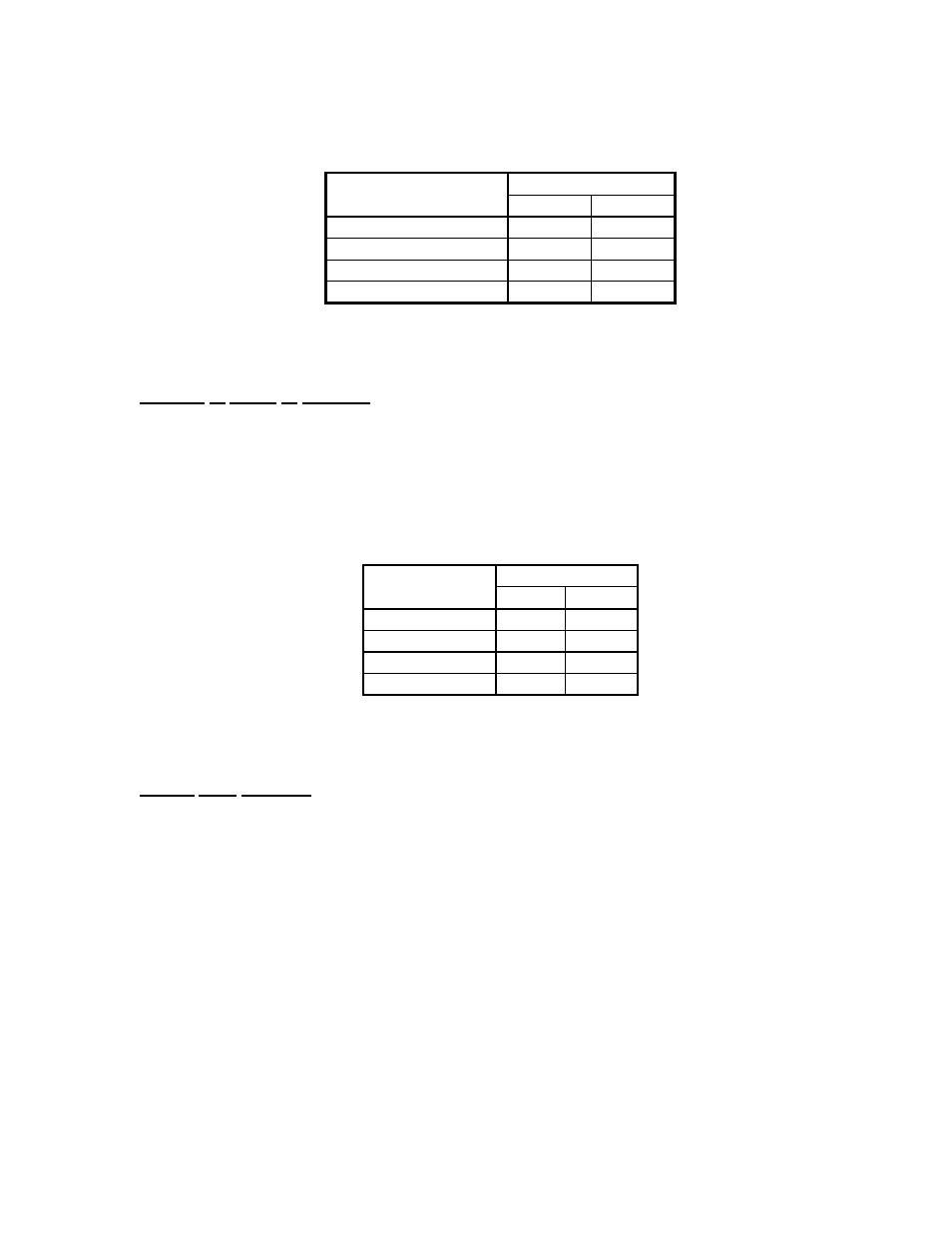
The programming of jumpers for the output relay is shown below. Consult FIGURE 3 page 7
for the 'J3' jumper and the 'J4' jumper location.
RELAY OUTPUT
JUMPER
MODE
J3
J4
LATCHING
O
O
MOMENTARY
X
O
ALTERNATE
O
X
20 MINUTE RESET
X
X
TABLE 2
X = JUMPER INSTALLED
O = JUMPER REMOVED
Number of Digits to Decode:
The 3185E is factory set to decode a 4-digit 'ON' code sequence and a 4-digit 'OFF' code
sequence. The first three digits of the code sequence are the same for both 'ON' and 'OFF'.
The fourth digit for the 'ON' code sequence is factory set to '*', and the fourth digit for the
'OFF' code sequence is factory set to '#'. The number of digits to decode is determined by
jumpers 'J6' and 'J5'. Consult FIGURE 3 page 7 for the location of 'J6' and 'J5'.
The programming of jumpers for the number of digits to decode is shown below:
NUMBER OF
JUMPER
DIGITS
J6
J5
1
X
X
2
X
O
3
O
X
4
O
O
TABLE 3
X = JUMPER INSTALLED
O = JUMPER REMOVED
Fourth Digit ON/OFF:
The fourth digit of the 'ON' code sequence and the fourth digit of the 'OFF' code sequence
are factory set at '*' and '#' respectively. To enable user selection of the fourth digits, it is
necessary to remove resistor ‘R8” and install two additional selection switches, S4 and S5,
plus IC A3. When ordering the switches, please use Monroe Electronics part number
‘9200002’ for each of the two switches and part number ‘9120375’ for the IC required.
Consult the PC board layout (3185E/22) for the location of the parts to be removed and
inserted.