Appendix a 1. connector pinouts – OT Systems ET1111 series User Manual
Page 18
ET1111 Series Installation & Operation Manual
A
Appendix A
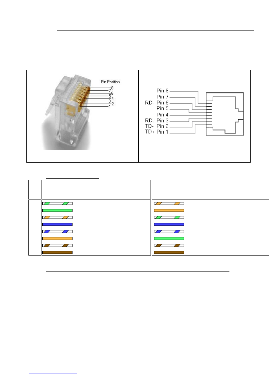
1. Connector Pinouts
RJ45 Connector (Male)
RJ45 Connector (Female)
2. TIA/EIA-568 Cabling
RJ45
Pin #
T568A
T568B
Wire Diagram Wire Color
10Base-T Signal
100Base-TX Signal
Wire Diagram
Wire Color
10Base-T Signal
100Base-TX Signal
1
White/Green Transmit+
White/Orange Transmit+
2
Green
Transmit-
Orange
Transmit-
3
White/Orange Receive+
White/Green
Receive+
4
Blue
Unused
Blue
Unused
5
White/Blue
Unused
White/Blue
Unused
6
Orange
Receive-
Green
Receive-
7
White/Brown Unused
White/Brown
Unused
8
Brown
Unused
Brown
Unused
3. Standard, Straight-Through Wiring Diagram(both ends are the same):
The Straight-Through wiring (or called “regular” Ethernet cable), both ends should be use the
same pin out on of RJ45 port.