Nstallation, Ount, Onnecting to – OT Systems ET1111 series User Manual
Page 9: Ower, Dc terminal block power input
ET1111 Series Installation & Operation Manual
9
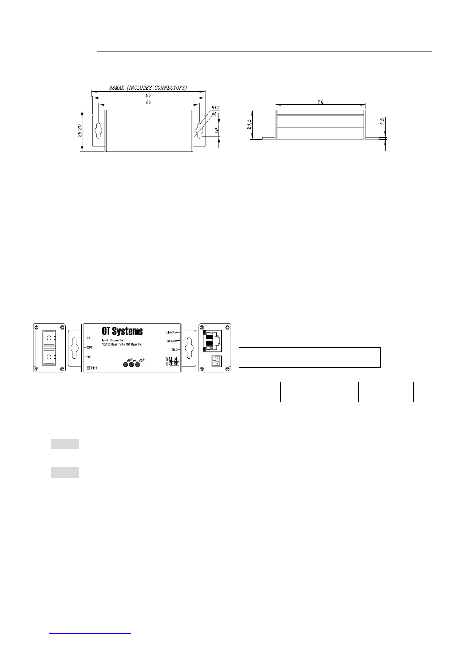
3.5 Installation- Wall Mount
(a) Top view
(b) Side view
Fig. 3.2 Dimension of Micro type units
Installation:
Mount the Micro type unit onto a fixture, or camera housings, e.g. a
plank, (either on the wall or on a flat surface) with at least 2 screws piercing through
the holes on the mounting frame to secure it in position.
Startup: Connect the supply voltage to start up the Media Converter via the terminal
block.
Removal: Locate and remove the securing screws. Usually, but not limited to, at
least 2 screws.
3.6 Connecting to Power
Bottom panel
– Ethernet Port and Power
Input
Ethernet Port
NETWORK -
RJ45
connector
Power Input Assignment
12VDC
1 GND
Terminal
Block
2 12V
Top Panel
Bottom Panel
DC Terminal Block Power Input
Step 1: Connect the DC power cord to the pluggable terminal block on the bottom of
Media Converter and then plug it into a standard DC outlet.
Step 2: Disconnect the power cord if you want to shut down the Media Converter.