Mpm-81 callouts, Page 2, Figure 1.1: rear panel view – Oxmoor MPM-81 User Manual
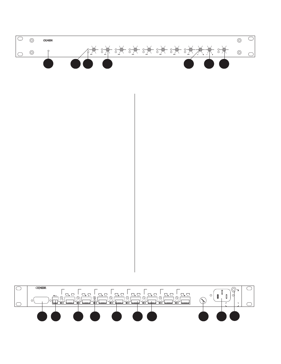
Page 4: Figure 1.0: front panel view
0
BASS
TREBLE
MIX LEVEL
0
0
0
CH 6 LEVEL
CH 7 LEVEL
CH 8 LEVEL
0
0
0
CH 3 LEVEL
CH 4 LEVEL
CH 5 LEVEL
0
CH 1 LEVEL
CH 2 LEVEL
0
PEAK
SIGNAL
MPM-81 MIXER
POWER
∞
Page 2
1
2
3
4
11. MIC/LINE TRIM
- Accessed with a small flat-blade
screwdriver. Adjusts the MIC/LINE input for varying
input signal levels over a ± 15 dB range.
12. CHANNEL IN
- Channel input, cage clamp connections
with mating connector, electronically balanced,
accommodates balanced or unbalanced signals. Normal
input level is dependent on the MIC/LINE switch setting.
Microphone input level is -40 dBu with a maximum input
level of -20 dBu. Line input level is +4 dBu with a
maximum input level of +18 dBu.
13. DIRECT OUT
- Direct audio output, cage clamp
connections with mating connector, electronically
balanced, accommodates balanced or unbalanced lines.
Recommended load impedance is 600 ohms or greater.
Maximum output level is +26 dBu.
14. MIX CONTROL
- Cage clamp connections with mating
connector. Provides a connection for jumper or external
switch to assign routing of the audio channel to the Mix
Bus. Latching contact closure required.
15. FUSE HOLDER -
Replace only with approved type of
fuse in a rating appropriate to the mains voltage, as
indicated on back panel. (See SPECIFICATIONS.)
16. POWER CONNECTOR
- Standard IEC 3-pin connector for
AC power cord. Use only with grounded (3-wire)
outlets. Cord sets are available for all world connection
standards.
17. CHASSIS GROUND POST
- A screw with a star washer
enables the installer to secure a ground wire to the
chassis.
1.
POWER STATUS LED
- Green LED Indicator for AC Power
On.
2.
PEAK INDICATOR
- Red LED Indicator for Peak audio
level.
3.
SIGNAL INDICATOR
- Amber LED Indicator for channel
signal present.
4.
CHANNEL VOLUME CONTROL
- Front panel volume
controls adjust the channel attenuation from 0 dBu to -80
dBu into the Mix Bus.
5.
BASS CONTROL
- Mix Bus bass control, ±12 dB boost/cut
at 150 Hz.
6.
TREBLE CONTROL
- Mix Bus treble control, ±12 boost/
cut at 8 kHz.
7.
MIX VOLUME CONTROL
- Front panel volume controls adjust
the Mix Bus attenuation from 0 dBu to -80 dBu.
8.
CONTROL PORT
- Female, 15-pin D-sub connector.
Provides connection for remote control of Channel
volume and Mix volume controls. Requires a DC voltage
between +15 VDC “Off” and 0 VDC “Full On.”
NOTE: The remote controls will be in parallel with the front
panel volume controls.
9.
MIX OUTPUT
- Mix audio output, cage clamp connections
with mating connector, electronically balanced,
accommodate balanced or unbalanced lines.
Recommended load impedance is 600 ohms or greater.
Maximum output level is +26 dBu.
10. MIC/LINE SWITCH
- Switch configures the MIC/LINE
input to accept either a microphone-level -40 dBu source
or a line-level +4 dBu source.
Figure 1.1: Rear Panel View
5
6
7
MPM-81 CALLOUTS
Figure 1.0: Front Panel View
13
15
10
11
12
16
17
8
9
CHASSIS
POWER
LINE/MIC
LINE/MIC
LINE/MIC
LINE/MIC
LINE/MIC
LINE/MIC
LINE/MIC
LINE/MIC
TRIM
TRIM
TRIM
TRIM
TRIM
TRIM
TRIM
TRIM
MIX
MIX
MIX
MIX
MIX
MIX
MIX
MIX
IN
IN
IN
IN
IN
IN
IN
IN
OUT
OUT
OUT
OUT
OUT
OUT
OUT
OUT
DIRECT
DIRECT
DIRECT
DIRECT
DIRECT
DIRECT
DIRECT
DIRECT
MIX OUT
FADER REMOTE
CHANNEL 8
CHANNEL 7
CHANNEL 6
CHANNEL 5
CHANNEL 4
CHANNEL 3
CHANNEL 2
CHANNEL 1
SERIAL #
®
MADE IN USA BY
OXMOOR CORPORATION
BIRMINGHAM, ALABAMA
........
.......
......
......
......
......
......
......
......
......
...
13
14