Mpm-81 set-up overview, Page 4, Example – Oxmoor MPM-81 User Manual
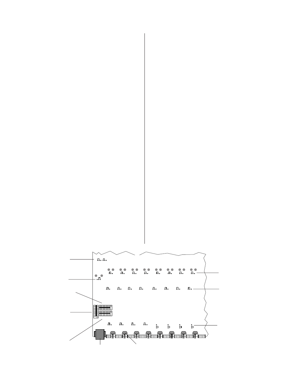
Page 6: Figure 2.0: printed circuit board top view, Jumpers show factory set-up
Page 4
MPM-81 SET-UP OVERVIEW
SET-UP DESCRIPTION
(Refer to Figure 2.0)
The MPM-81 has three internal dip switches that may be used to
configure its operation for different system requirements. In
addition there are four groups of jumpers that allow you to
assign Phantom Power to each input, insert Hi-Pass filters to
each channel, Balance or Unbalance each output, and bypass the
Tone Controls on the Mix output.
Before installing the MPM-81, refer to the description below and
determine the switch positions best suited to your system
requirements. Use Figure 3.0 on page 5 as the User Set-Up
Template for configuring the unit.
SW 9 SELECT PAGE CHANNEL
(Refer to Figure 2.0)
Switch SW 9 determines which of the eight input channels “1
through 8” will be used to activate the page function.
Example:
If channel one is to be used as the Page channel, set SW 9 switch
1 to “ON.” When channel one’s MIX control line is taken to
common using a maintained closure, then the following two
functions result:
A. Channel one is sent to the Mix Bus.
B.
All channels that have been programmed to mute (see
SW 10 below) will mute their audio as long as channel
one’s mix control is maintained to common.
SW 10 SELECT CHANNELS TO MUTE
(Refer to Figure 2.0)
Switch SW 10 determines which of the eight channels will be
muted when the page input channel is activated.
Example:
If channels 2, 3 and 4 are required to mute, set SW 10 switches 2,
3, and 4 to “ON.” When the assigned page channel (see SW 9
above) is activated, then channels 2, 3, and 4 will mute as long
as the assigned page channel is active.
Figure 2.0: Printed Circuit Board Top View
SW 11 ASSIGN CHANNELS TO THE MIX BUS
(Refer to Figure 2.0)
SW 11 assigns channels 1 through 8 to the MIX Bus.
Example:
If channels 6, 7 and 8 are required to be assigned permanently to
the Mix Bus, set SW 11 switches 6, 7, and 8 to “ON.”
NOTE: If channel 6, 7 or 8 is programmed as an Activate Duck
Channel (see SW 9) then all channels that are programmed to duck
(see SW 10) are ducked as long as the Activate Duck Channel is
assigned to the Mix Bus.
MICROPHONE PHANTOM POWER SELECT
(Refer to Figure 2.0)
A jumper is provided for each channel to assign phantom
power to the channel. The MPM-81 is factory-configured with
the phantom power OFF.
CHANNEL HI-PASS FILTER SELECT
(Refer to Figure 2.0)
A jumper is provided for each channel to allow insertion of a
230 Hz Hi-Pass filter. The MPM-81 is factory-configured with
the Hi-Pass filters bypassed.
OUTPUT BALANCED/UNBALANCED SET-UP
(Refer to Figure 2.0)
A jumper is provided for each channel to allow easy conversion
to a balanced or unbalanced output configuration. The MPM-81
is configured from the factory for balanced audio outputs.
MIX BUS TONE CONTROLS BYPASS
(Refer to Figure 2.0)
A jumper is provided for bypass of the Mix Bus Bass and Treble
controls. The MPM-81 is factory-configured with the Mix Bus
Bass and Treble controls active.
123
4
5
6
7
8
ON
1
2
34
5
6
7
8
ON
1
2
34
5
6
7
8
ON
SW 9
SW 11
SW 10
IN
OUT
OUT
OUT
OUT
OUT
OUT
OUT
OUT
J13
J12
J16
J11
J15
J14
J10
J17
J22
J21
J25
J20
J24
J23
J19
J26
OFF
OFF
OFF
OFF
OFF
OFF
OFF
OFF
J9
J2
J6
J3
J8
J4
J5
J7
CH 1
CH 2
CH 3
CH 4
CH 5
CH 6
CH 7
CH 8
J28
J18
J27
Bal.
Bal.
Bal.
Bal.
Bal.
Bal.
Bal.
Bal.
Bal.
Control Port
Mic/Line Trim Pots
Microphone Phantom Select
HI-Pass Filters Select
Channel Bal/Unbalance Select
Mix Bus Bal/Unbalance Select
Mix Bus Tone Controls bypass
SW 9 Channel To Activate Duck
SW 10 Channel To Duck Select
SW 11 Mix Bus Assignment Select
Jumpers Show Factory Set-Up