Pengo OMA-250H User Manual
Page 8
8
OMA-250H
(135473.indd)
(135473.indd)
OMA-250H
13
3) OPERA
TION (DRILLING)
W
ARNING!
Do not touch or grasp the auger bit when engine is running.
Be sure to turn of
f the ignition switch.
1. Do not operate the unit with others nearby
. Caution
all near the operation of the unit to stand clear
. Keep
all body parts, loose clothing, and foreign objects clear
of the rotating auger bit. Do not use a shovel to remove
loose soil from the hole area while the unit is operating.
By doing so the shovel may become entangled by the
rotating auger bit, causing possible property damage and
or personal injury
.
2. Start and operate the unit only in a well ventilated,
outdoor area. Operate the unit only when suf
fi cient
light
is available.
Always hold the unit
fi rmly with both hands.
Be sure the handles are free from any substance that may
cause the operator to lose his or her grip on the handles.
W
ear gloves to improve your grip during operation. Never
leave the unit unattended while the engine is running.
3. Stop the unit between each hole to minimize the
potential for danger
. Special care must be used in slippery
conditions and in dif
fi cult or overgrown terrain. W
atch for
hidden obstacles such as tree stumps and tree roots. Be
sure to keep proper footing and balance during operation.
Normal use for this unit is on level ground. Other terrains
can be dangerous. Use good judgement.
4.
To
stop the unit gradually decrease the engine speed
to an idle and release the auto stop trigger
.
TIPS FOR DRILLING
Before starting any drilling!
Contact your local utility
company and have all gas, power
, telephone and water
lines located.
Lower the
Auger unit slowly and let the auger bit do the
work. Do not allow the auger to quickly corkscrew into
the ground.
The auger must be lowered in a controlled
manner to facilitate the removal of spoils and avoid stalling
the unit.
As you drill, depending on the bit size, you may need to
raise the auger bit to clean the
fl ights as you progress
into the hole.
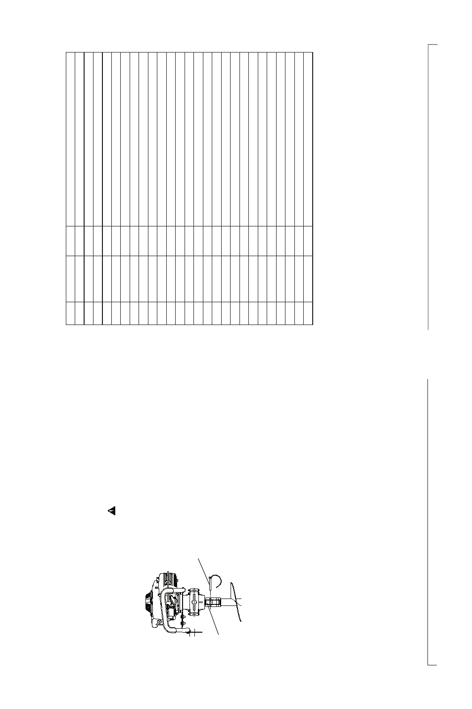
1) CONNECTION
Connect the auger bit to the drive shaft
[A]
of the power
head and secure it with the appropriate connecting
hardware
[B]
. (See
fi gure
4)
2) SELECTION OF
AUGER BIT
Choose an auger bit (8” Max Dia.) according to the type
of material to be drilled. For ice drilling, use an ice auger
.
When drilling in dirt or other earth type materials use an
earth auger
.
1) FUELING
Gasoline is an extremely flammable fuel. Use cau-
tion when handling the fuel.
Always use an approved
container for the handling, storage, and transportation
of fuel.
•
Always shut of
f the engine before refueling.
• Slowly open the fuel tank, when
fi lling up with fuel, so
that possible over-pressure disappears.
•
T
ighten the fuel cap carefully
, after fueling.
• Move the unit at least 10 ft. (3 m) from the fueling area
before starting the unit.
Before fueling, clean the tank cap area, to ensure that
no dirt falls into the tank.
2) ST
ARTING
1. Set the gas supply switch to the open position.
2. Pull the auto stop trigger and keep the trigger
collapsed.
3. Set the choke lever to desired position.
4. Pull the recoil starter handle briskly
. Keep a good grip
on the handle. Do not allow the handle to snap back.
Figure 4
A
B
5. Once the engine is running, adjust the choke to the
original position.
6.
After starting the engine, allow the unit run for 1-2 minuets
before operating. (warm-up period)
ASSEMBL
Y
PROCEDURE
OPERA
TING PROCEDURES
ITEM
P
ART No.
QTY
DESCRIPTION
1
260038
4
W
ASHER, CTRSK EXT
. T
OOTH LOCK 6mm
2
260004
1
GASKET
, TRANSMISSION
CASE
3
260033
8
W
ASHER, FLA
T
6mm
4
26001
1
6
W
ASHER, LOCK 6mm
5
260031
2
SCREW
, HEX HEAD M6x1 6mm LONG
6
260032
2
PIN, DOWEL
GEARBOX LINE-UP
7
260013
4
BEARING, CLUTCH SHAFT
8
260082
1
RING, SNAP
40 INTERNAL
9
260017
1
GEAR, PRIMAR
Y
PINION
10
260018
1
GEAR, PRIMAR
Y
73
T
OOTH
11
260021
1
KEY
, WOODRUF
12
260026
1
GEAR, SECONDAR
Y
PINION
13
260027
1
KEY
, SQUARE
14
260028
1
GEAR, SECONDAR
Y
73
T
OOTH
15
260029
1
W
ASHER, THRUST
16
260014
3
SNAP
RING, OUTPUT
SHAFT
17
260030
2
BEARING, OUTPUT
SHAFT
18
260015
4
SCREW
, FLA
T
HEAD HEX SOCKET
19
260010
6
NUT
, HEX M6x1
20
260035
6
SCREW
, HEX M6x1 x 60mm
21
260007
1
COVER, TRANSMISSION
22
260008
1
CASE, TRANSMISSION
23
260034
1
SHAFT
, OUTPUT
24
260016
1
SHAFT
, INPUT
& CLUTCH CUP
25
260080
1
S
P
ACER, BEARING (761400)
26
260081
1
S
P
ACER, BEARING (761401)
OMA-250H GEARBOX P
ARTS LIST BY
KIT
REPLACEMENT
ITEMS CAN BE ORDERED IN REP
AIR KITS LISTED ON P
AGES 14 &
15
135473-OMA.indd, Spread 8 of 10 - P
ages (8, 13) 1/9/2007 2:50 PM