Daviscomms (s) pte ltd – WaveWare TMR1P User Manual
Page 18
DAVISCOMMS (S) PTE LTD
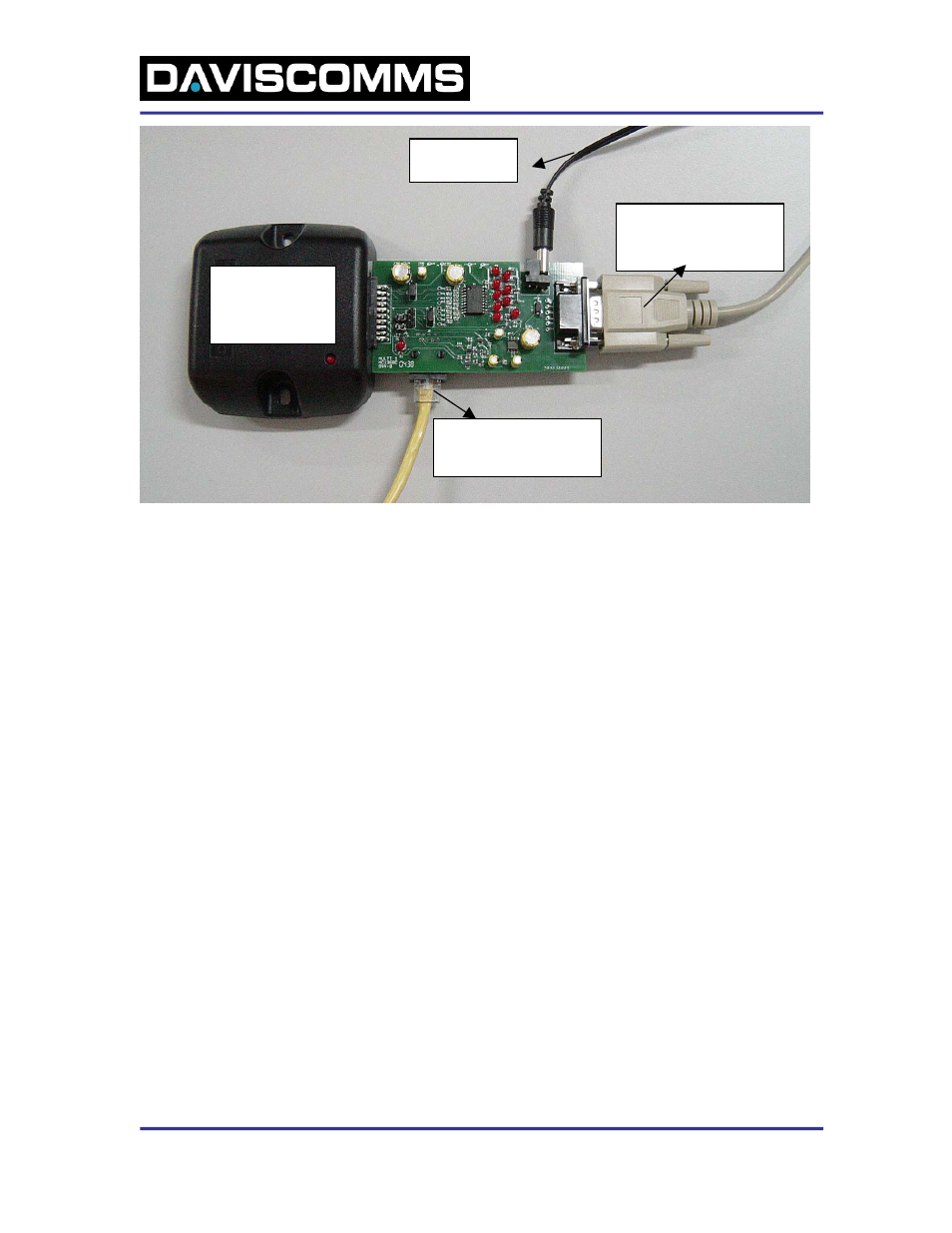
12VDC power
adapter
D-sub 9-pin Serial cable
(male) to connector on
the Evaluation Board
Telemetry
Message Receiver
(TMR Module)
RJ-45 cable to the RJ-45
connector on the
Evaluation Board
Figure 1. Evaluation Kit set-up with TMR module, Evaluation Board and various cables.
1. Plug the TMR module 20-pin connector into the Evaluation Board 20 pins connector (Fig. 1).
2. Connect RJ-45 connector to the RJ-45 Jack on the Evaluation Board (Fig. 1). Connect DB25-
pin connector of the programming cable to Parallel Port on PC (Fig.2). (This connection need
only be made if the TMR will be re-programmed with a new frequency or CAP code.)
3. Connect the male portion of the D-Sub 9-pins serial cable to connector on the Evaluation
Board (Fig. 1). Connect female portion of the D-Sub 9-pins serial cable to the Serial Ports (COM
ports) on PC (Fig.2).
4. Connect power connector (12Vdc adapter) into power jack on the Evaluation Board.
5. The power LED will light on the Evaluation Board and on the TMR module.
18
500088R03
DAVISCOMMS (S) PTE LTD
Blk70 Ubi Crescent #01-07 Singapore 408570. Tel: (65) 65471127 Fax: (65) 65471129